

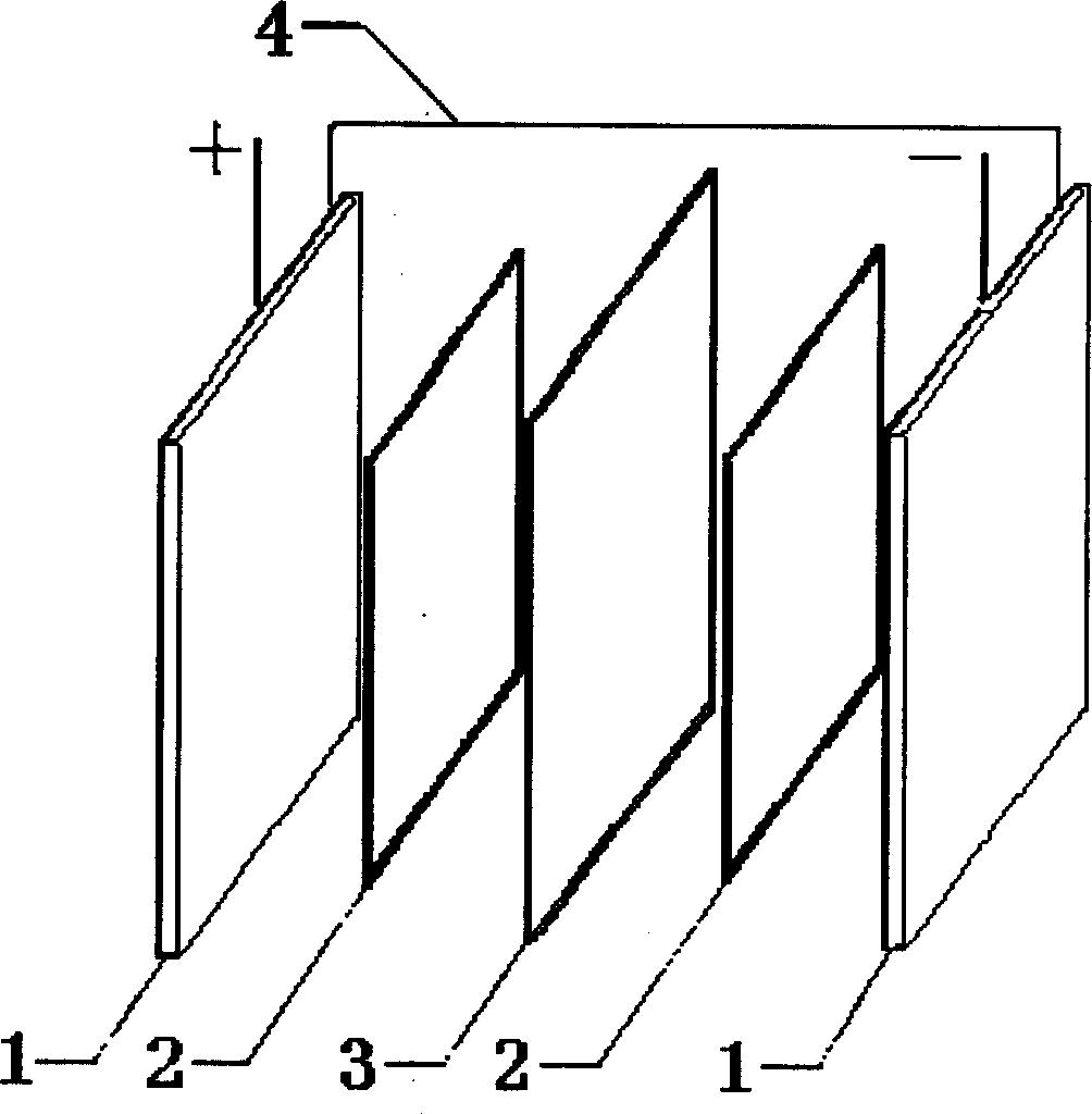
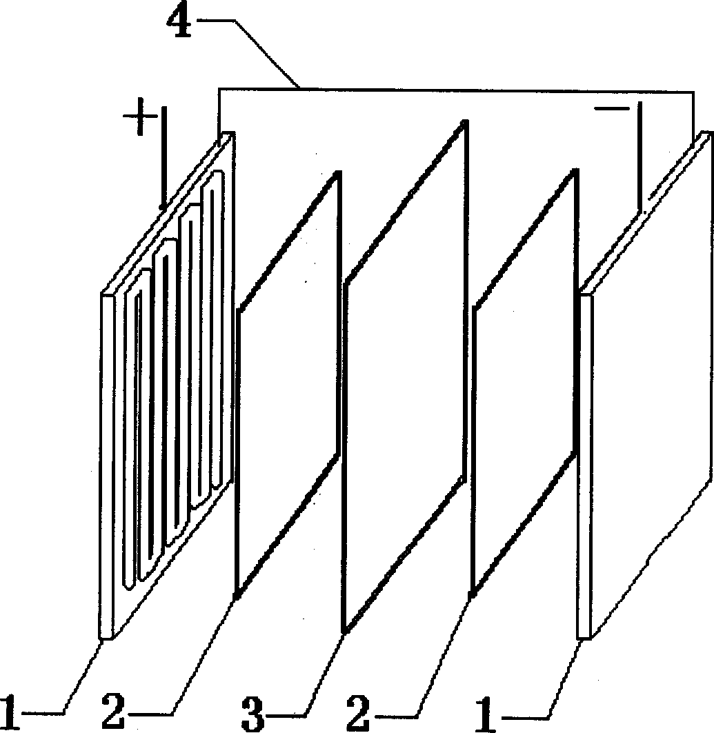
Current collection plate for all vanadium redox flow battery
A liquid flow battery and current collector technology, which is applied in fuel cells, battery electrodes, electrode carriers/collectors, etc., can solve problems such as easy deformation, poor charge and discharge capacity, and difficult sealing of batteries, and achieve high rigidity and strength. The effect of stable chemical performance and strong charge and discharge ability
- Summary
- Abstract
- Description
- Claims
- Application Information
AI Technical Summary
Problems solved by technology
Method used
Image

Examples
example 1
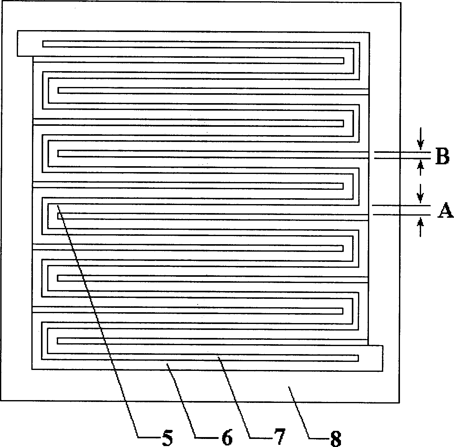
[0019] Example 1: A high-density graphite plate impregnated with epoxy resin is used as a collector plate, and a serpentine flow field is engraved on the collector plate. The length of the flow field is 120mm, the width is 120mm, and the width of the outer edge 8 of the flow field is 15mm ; The ratio of ridge width to groove width in flow field is 1:6, and the ratio of groove depth to groove width in flow field is 1:5. The current collector plate, electrode and separator were assembled into an all-vanadium redox flow battery, and the charge and discharge test was carried out. The average coulombic efficiency of the first five charge and discharge was 89.1%.
example 2
[0020] Example 2: A high-density graphite plate impregnated with phenolic resin is used as a collector plate, and eight parallel serpentine flow fields are engraved on the collector plate. The length of the flow field is 120mm, the width is 170mm, and the width of the outer edge 8 of the flow field is 15mm ; The ratio of flow field ridge width to groove width is 1:0.5, and the ratio of flow field groove depth to groove width is 1:1. The current collector plate, electrode and separator were assembled into an all-vanadium redox flow battery, and the charge and discharge test was carried out. The average coulombic efficiency of the first five charge and discharge was 86.5%.
example 3
[0021] Example 3: A high-density graphite plate impregnated with epoxy resin is used as a collector plate, and four parallel serpentine flow fields are engraved on the collector plate. The length of the flow field is 260 mm, and the width is 260 mm. The width of the outer edge 8 of the flow field is 20mm; the ratio of flow field ridge width to groove width is 1:3.3, and the ratio of flow field groove depth to groove width is 1:3.3. The current collecting plate, electrode and diaphragm were assembled into an all-vanadium redox flow battery, and the charge and discharge test was carried out. The average coulombic efficiency of the first five charge and discharge was 95.8%.
PUM
| Property | Measurement | Unit |
|---|---|---|
| current efficiency | aaaaa | aaaaa |
| current efficiency | aaaaa | aaaaa |
| current efficiency | aaaaa | aaaaa |
Abstract
Description
Claims
Application Information