Magnetic suspension bearing differential transformer type displacement sensor

A differential transformer type, displacement sensor technology, applied in the field of displacement sensors, can solve the problems of increased system cost, troublesome assembly process, loose sensor, etc., and achieves the effects of reliable performance, simple circuit and large inductance

Inactive Publication Date: 2006-10-25
NANJING UNIV OF AERONAUTICS & ASTRONAUTICS
View PDF0 Cites 19 Cited by
  • Summary
  • Abstract
  • Description
  • Claims
  • Application Information

AI Technical Summary

Problems solved by technology

At present, eddy current sensors are commonly used in magnetic suspension bearing systems, but many inconveniences are found in the process of using eddy current sensors: for a five-degree-of-freedom magnetic suspension bearing system, 10 sensors are required, and the number of sensors is large, not only The cost of the whole system is increased, and unreliable factors are also added; the eddy current sensor measures the movement of the rotor surface, which can only indirectly reflect the position of the rotor center. When the rotor rotates, it reflects the rotor whirl ;The eddy current sensor is fixed on the sensor bracket through threaded connection, the assembly process is more troublesome and the sensor will loosen when the system vibrates or other reasons; for some special applications, such as dustproof, isolation, etc. When a metal protective film is added between the stators of magnetic suspension bearings, the eddy current sensor is not competent

Method used


Image

  • Magnetic suspension bearing differential transformer type displacement sensor
  • Magnetic suspension bearing differential transformer type displacement sensor
  • Magnetic suspension bearing differential transformer type displacement sensor

Examples


Embodiment Construction

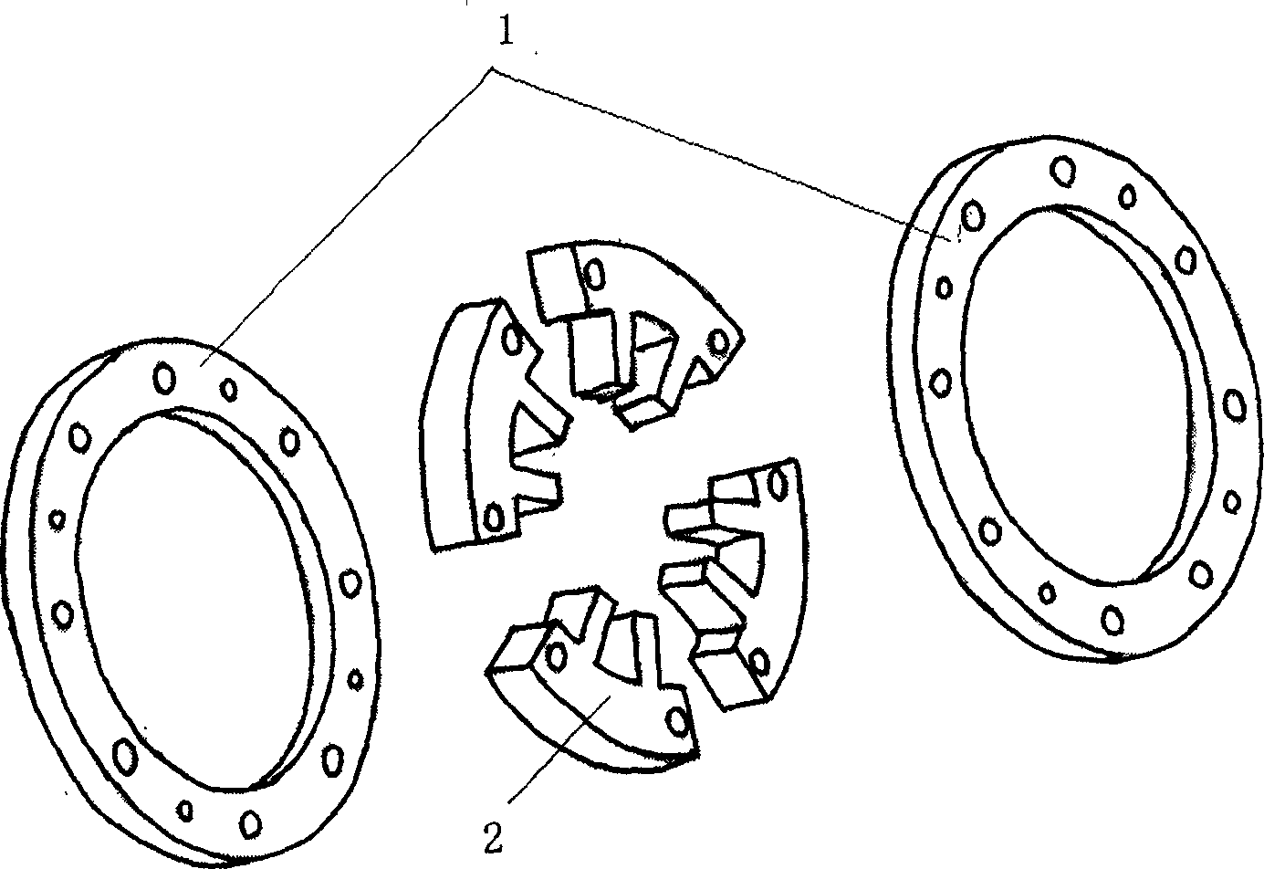
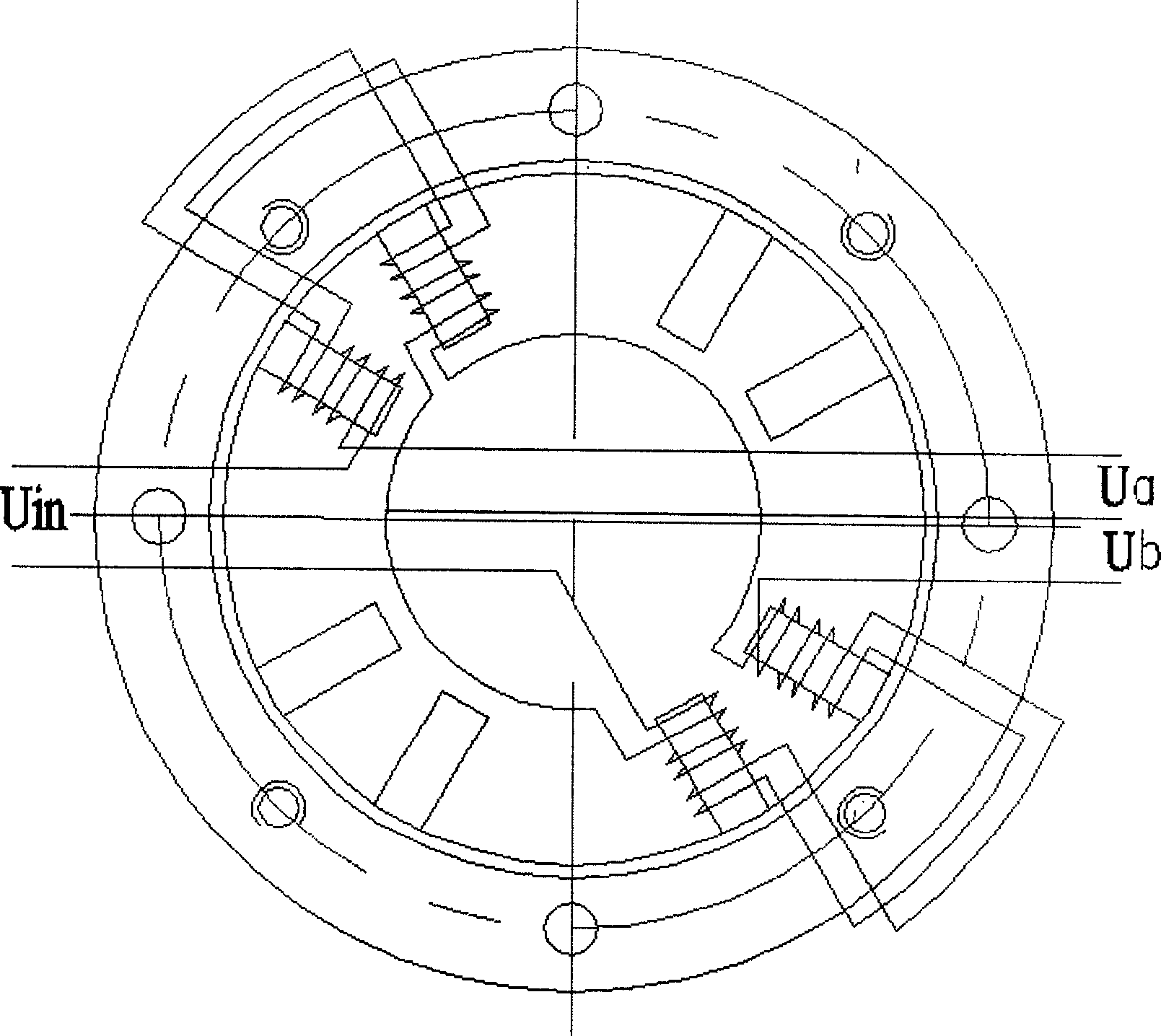
[0017] like figure 1 As shown, the mechanical structure of the differential transformer of the present invention consists of a splint 1 and a magnetic core 2 . The magnetic core 2 is formed by stacking iron-nickel alloy 1J79 circular laminations with a thickness of 0.05mm. A certain number of 1J79 laminations are laminated to a certain thickness and pressed tightly; The two ends of the core, and fix the two splints and the magnetic core with rivets; then perform wire cutting, cut out the outer circle and magnetic poles; figure 1 The shape of the middle magnetic core; finally grind the outer circle and the inner circle of the pole. Use polytetrafluoroethylene or plastic to process the coil frame of the transformer, and use QZ type high-strength enameled wire with a wire diameter of 0.23mm to wind in parallel for 50 turns. After the coil is wound, before assembly, it is necessary to ensure that each coil is available, that is, to ensure that each coil is conductive (not discon...


PUM


Abstract

The invention discloses a magnetic suspension bearing differential transformer displacement sensor that includes differential transformer and detecting circuit. The detecting circuit includes sine wave generating circuit, current amplification circuit, detecting circuit, and low passing filter circuit. The sine wave would be amplified and generate the magnetic flux of the primary coil of the transformer. The alteration of the displacement of the rotator would cause the alteration of mutual inductance between primary coil and secondary primary to generate the corresponding alteration of the secondary coil induced voltage that could form the DC voltage signal of the rotator. The invention has bright application prospect in magnetic suspension bearing. It could also be used to measure other type linear movement or anger movement after taking a little modification.

Description

1. Technical field [0001] The invention belongs to a displacement sensor, in particular to a radial displacement sensor applied to a magnetic suspension bearing. 2. Background technology [0002] Magnetic suspension bearing is a new type of high-performance bearing that uses magnetic force to suspend the rotor in space, so that there is no mechanical friction support between the rotor and the stator. Compared with traditional rolling bearings and sliding bearings, the obvious feature of magnetic suspension bearings is that there is no mechanical contact, and its supporting force is controllable, without mechanical friction and wear, thus reducing working energy consumption and noise, prolonging service life, and small power loss , suitable for application in high-speed operation occasions; since the lubrication and sealing system are omitted, there is no pollution, and it can be used in special working environments such as vacuum ultra-clean and extreme temperature and press...

Claims


Application Information

Patent Timeline
Patent Type & Authority Applications(China)
IPC IPC(8): G01B7/02
Inventor 徐龙祥金超武
Owner NANJING UNIV OF AERONAUTICS & ASTRONAUTICS
Why Eureka
Try Eureka