Full-fiedl correction method for laser scanning cofocal microscope scanning distortion phenomenon

A confocal microscope and laser scanning technology, applied in the field of full-field correction, can solve the problems of complexity, inability to correct, reduce scanning speed, etc., and achieve the effect of simple operation and high precision

Inactive Publication Date: 2006-10-25
TSINGHUA UNIV
View PDF0 Cites 11 Cited by
  • Summary
  • Abstract
  • Description
  • Claims
  • Application Information

AI Technical Summary

Problems solved by technology

The error correction methods of traditional stepping motors include: using high-precision stepping motors, according to the required accuracy, you can choose stepping motors with high precision and small errors as much as possible to reduce the distortion of the system, but this method does not eradicate stepping motors. The error of the stepper motor is only reduced by using a high-precision stepper motor; the design of a high-precision control circuit to control the error of the stepper motor, such as the common subdivision drive method, reduces the step Long to reduce the error caused by uneven step length, but this method also has its limitations, that is, the uneven step length of the motor in high-speed rotation will cause high vibration, resulting in system instability, so Using this method will reduce the scanning speed; now the most effective and common method is to perform closed-loop control on the motor, obtain a compensation current through circuit control, and realize the control of the motor error by increasing the compensation current on the basis of the original current. , this method is relatively complicated to implement and requires complex circuit design. At the same time, the correction of the error can only be an offline state correction. Error phenomenon, and this correction is more of an average result, and it is impossible to achieve point-by-point full-field correction
[0006] The above method can only eliminate the error within a certain limit, but there is no way to quantify this error. At the same time, most of the methods used are offline corrections, which cannot be corrected under actual working conditions. Therefore, in the actual scanning process, especially high-speed scanning This image distortion cannot be corrected during the

Method used


Image

  • Full-fiedl correction method for laser scanning cofocal microscope scanning distortion phenomenon
  • Full-fiedl correction method for laser scanning cofocal microscope scanning distortion phenomenon
  • Full-fiedl correction method for laser scanning cofocal microscope scanning distortion phenomenon

Examples


Embodiment Construction

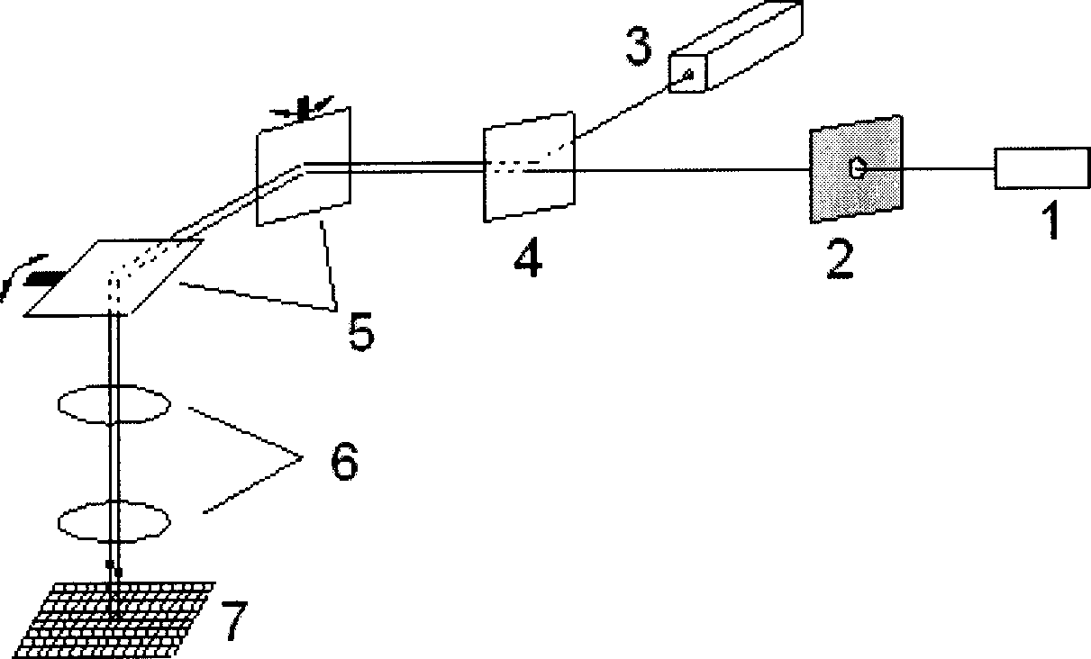
[0024] The principle and specific implementation method of the present invention will be further described below in conjunction with the accompanying drawings.

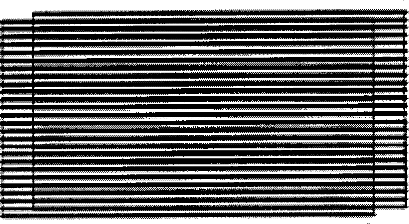
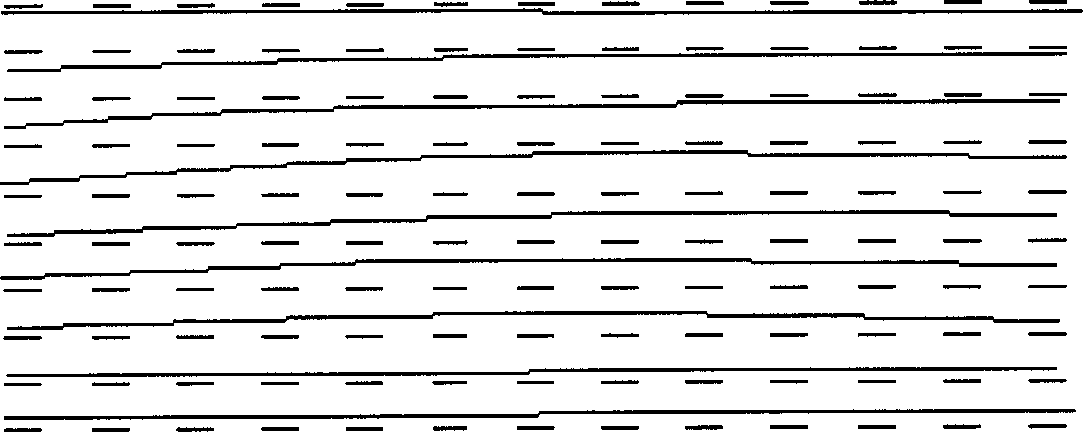
[0025] In order to achieve the above-mentioned purpose of the invention. The present invention needs to adopt a one-dimensional standard grating specimen, use the LSCM scanning moiré method to obtain the scanning moiré, and then obtain the displacement field information of the whole field area through the moiré phase shift method, and extract the distortion information of the scanning control unit, thereby achieve the purpose of calibration. The scanning moiré method is a geometric moiré method realized in a high-power microscope based on the principle of the traditional moiré method. The main principle is to form a specimen grating on the surface of the sample by etching or transferring the grating. The lines are scanned line by line according to certain rules, so a reference grid will be formed on the surface of th...


PUM


Abstract

The present invention adopts standard raster specimen, using LSCM scanning moire method to obtain scanning moire image, to proceed four steps phase shift processing to originality image though moire phase shift technology to obtain phase shift moire image, according to moire phase shift theory to obtain phase map, after unpackaging to obtain originality phase map, according to phase and displacement field relation to obtain scanning perturbed field, thereby reaching correction target. Compared with current method, the present invention can directly measure scan line perturbed field resulted from scanning control unit distortion phenomena through scanning moire and moire phase shift technology , with high precision, simple operation, and real time and all field measurement.

Description

technical field [0001] The invention relates to a full-field correction technology of a laser scanning confocal microscope. Background technique [0002] With the rapid development of science and technology, microscopes with high image resolution have become effective tools for scientists to conduct scientific research. Laser Scanning Confocal Microscopy (LSCM) developed in the 1980s is an advanced image acquisition and analysis instrument in the field of biological research, and is widely used in various fields of biology, such as : Cytoskeleton research, physiological and biochemical research, gene positioning and chromosome three-dimensional mapping, embryology research, botany research, etc. The spatial resolution of the traditional optical microscope is limited due to the limitation of the diffraction limit, while the laser scanning confocal microscope uses the laser as the illumination source, and adopts the principle of conjugate focusing and scanning imaging device ...

Claims


Application Information

Patent Timeline
Patent Type & Authority Applications(China)
IPC IPC(8): G02B21/00
Inventor 谢惠民花韬方岱宁潘兵
Owner TSINGHUA UNIV
Why Eureka
Try Eureka