Piezoelectric vibrator and its fabricating method, piezoelectric oscillator, electronic apparatus and radio wave timepiece
A piezoelectric and vibrator technology, applied in the direction of electrical components, impedance networks, etc., can solve problems such as oscillation instability and frequency offset, and achieve the effect of suppressing the reduction of production efficiency
- Summary
- Abstract
- Description
- Claims
- Application Information
AI Technical Summary
Problems solved by technology
Method used
Image
Examples
Embodiment 1
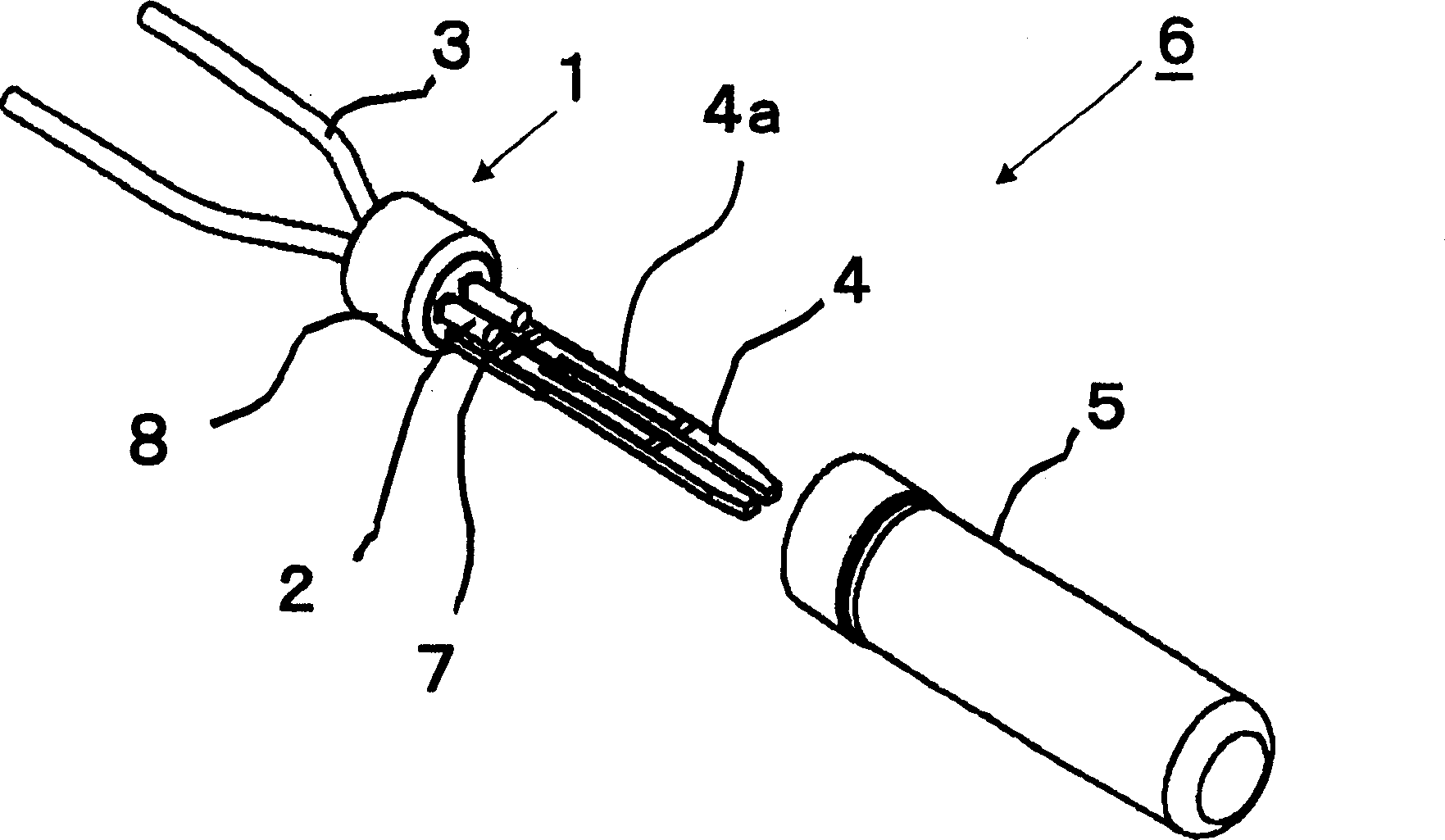
[0064] figure 1 is an exploded perspective view showing the configuration of the piezoelectric vibrator according to the first embodiment.
[0065] like figure 1 As shown, the piezoelectric vibrator 6 is composed of an airtight terminal 1, a piezoelectric vibrating piece 4 made of a piezoelectric material such as quartz, and a sealing tube 5 of a cylindrical cylindrical bottom member made of metal. In addition, the airtight terminal 1 includes an annular stem 8 made of metal material, and two lead terminals passing through the stem 8 . The shorter ends of the two lead terminals welded to the piezoelectric vibrating piece 4 and included in the sealed tube 5 constitute the inner lead 2 , and the longer ends protruding to the outside constitute the outer lead 3 . The surface of the lead terminal and the outer edge of the stem 8 are plated.
[0066] The piezoelectric vibrating piece 4 of the present embodiment is a tuning-fork type vibrating piece having a base portion and a ...
Embodiment 2
[0107] Figure 10 is a schematic outline diagram showing the constitution of a tuning fork type quartz crystal oscillator according to the present invention, and is using the tuning fork type quartz crystal oscillator having inner leads and mounting electrodes welded by the welding method explained in Embodiment 1, A plan view of a surface mount piezoelectric oscillator.
[0108] exist Figure 10 In, a tuning-fork type quartz crystal oscillator 51 is set to a predetermined position on a circuit board 52, and an oscillator integrated circuit indicated by reference numeral 53 is mounted adjacent to the quartz crystal oscillator. In addition, electronic components 54 such as capacitors are mounted. The various components are electrically connected by wiring diagrams, not shown. The mechanical vibration of the piezoelectric vibrating piece of the tuning-fork type quartz crystal vibrator 51 is converted into an electrical signal to be input to the integrated circuit 53 by the pi...
Embodiment 3
[0111] Next, an explanation will be given of an example of an electronic device using a piezoelectric vibrator manufactured by the manufacturing method of the present invention. Here, a detailed explanation will be given of a preferred embodiment of a portable information device represented by a portable telephone.
[0112] First, as a premise, the portable information device according to the present embodiment is constructed by developing and improving related art wristwatches. Its appearance is similar to that of a watch, and a liquid crystal display is arranged on its part corresponding to the dial, so that the current time and the like can be displayed on its screen. When used as a communication device, the device is detached from the wrist, and communication similar to that of a related art portable phone is enabled through a speaker and a microphone contained inside the belt portion. However, the device is remarkably small and light in weight compared with the related a...
PUM
 Abstract
Description
Claims
Application Information
 - R&D
- Intellectual Property
- Life Sciences
- Materials
- Tech Scout
- Unparalleled Data Quality
- Higher Quality Content
- 60% Fewer Hallucinations
Browse by: Latest US Patents, China's latest patents, Technical Efficacy Thesaurus, Application Domain, Technology Topic, Popular Technical Reports.
© 2025 PatSnap. All rights reserved.Legal|Privacy policy|Modern Slavery Act Transparency Statement|Sitemap|About US| Contact US: help@patsnap.com


