

Precision shaping method of solid bearing holder
A solid cage and precision forming technology, applied in the field of bearing cage forming, can solve problems such as difficult large-scale production, increased processing costs, and complicated processes, and achieve reduced processing costs, improved production efficiency, and high surface quality. Effect
- Summary
- Abstract
- Description
- Claims
- Application Information
AI Technical Summary
Problems solved by technology
Method used
Image

Examples
Embodiment 1
[0014] The blank used in this embodiment is a brass HPb59-1 casting pipe material, which is turned into a ring-shaped blank. The blanking volume of the blank should include the body part of the cage, the end cover part, the cutting edge material for the separation process, and the remaining material after cutting.
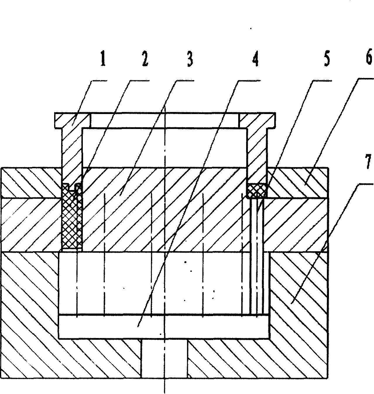
[0015] Preheat the blank to 120°C and apply water agent graphite lubricant, put the blank into a box-type electric furnace, heat it to 620°C, keep it warm for 20 minutes, and then put it into a mold with a temperature of 580°C to deform the blank and fill the cavity of the die And take shape. The press machine that present embodiment adopts is hydraulic press. Mold such as figure 1 As shown: the extrusion forming part is mainly composed of a pressure head 1, a die 3, an ejector 4, a small ejector rod 5, an extrusion sleeve 6, and a lower die base 7. Among them, the indenter 1 is fixed on the movable beam of the press through a fixing device; the die 3 is located...
Embodiment 2
[0018] The blank used in this embodiment is a brass HPb59-1 extruded pipe material, which is turned into a ring-shaped blank. The blanking volume of the blank should include the body part of the cage, the end cover part, the cutting edge material for the separation process, and the remaining material after cutting.
[0019] Preheat the blank to 180°C and apply water-based graphite lubricant, put the blank into a box-type electric furnace, heat it to 650°C, keep it warm for 15 minutes, and then put it into a mold with a temperature of 620°C at a working speed of 2 mm / s , The pressure of 15MPa deforms the blank and fills the cavity of the die to complete the extrusion process. The press used in this embodiment is a conventional press. Its structure and working process are with embodiment 1.
Embodiment 3
[0021] The blank used in this embodiment is a brass HPb59-1 casting pipe material, which is turned into a ring-shaped blank. The blanking volume of the blank should include the body part of the cage, the end cover part, the cutting edge material for the separation process, and the remaining material after cutting.
[0022] Preheat the blank to 220°C and apply water-based graphite lubricant, put the blank into a box-type electric furnace, heat it to 680°C, keep it warm for 15 minutes, and then put it into a mold with a temperature of 650°C at a working speed of 2 mm / s , The pressure of 12MPa deforms the blank and fills the cavity of the die to complete the extrusion process. The press used in this embodiment is a conventional press. Its structure and working process are with embodiment 1.
PUM
 Abstract
Description
Claims
Application Information