Antenna coil and RFID-use tag using it, transponder-use antenna

A technology of antenna coils and transponders, which can be used in the direction of electrical alarms, record carriers used by machines, and mid-position feeds between antenna terminals, which can solve problems such as large intervals

Inactive Publication Date: 2006-11-29
MITSUBISHI MATERIALS CORP
View PDF1 Cites 60 Cited by
  • Summary
  • Abstract
  • Description
  • Claims
  • Application Information

AI Technical Summary

Problems solved by technology

[0022] However, in the above-mentioned conventional transponder, since the thickness of the partition plate is relatively thick, even if the antenna itself is as thin as possible, the distance between the metal object and the transponder will still be relatively large, and there will still be problems with the transponder from management. Significantly prominent defects on the subject article

Method used


Image

  • Antenna coil and RFID-use tag using it, transponder-use antenna
  • Antenna coil and RFID-use tag using it, transponder-use antenna
  • Antenna coil and RFID-use tag using it, transponder-use antenna

Examples


experiment example 1

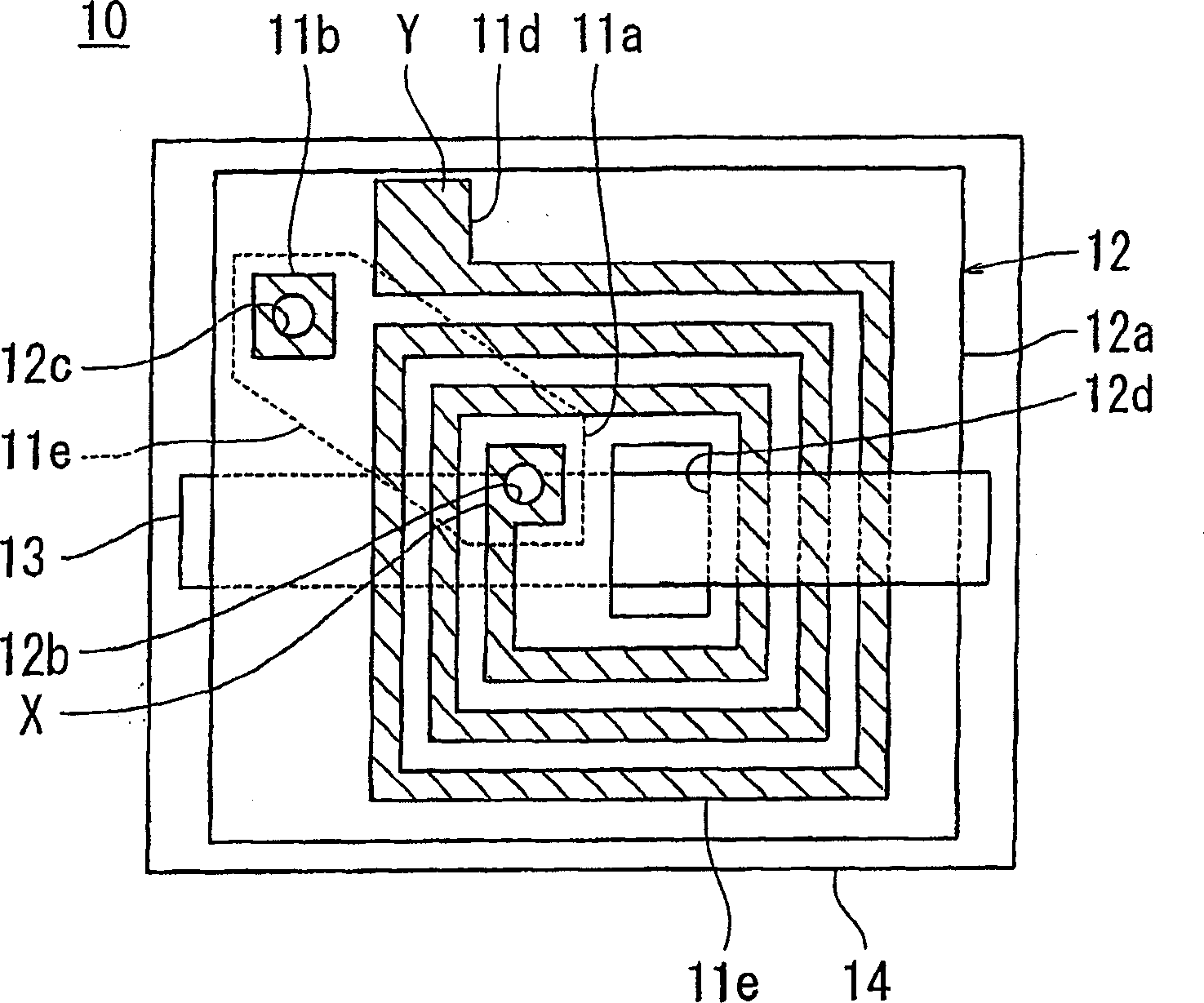
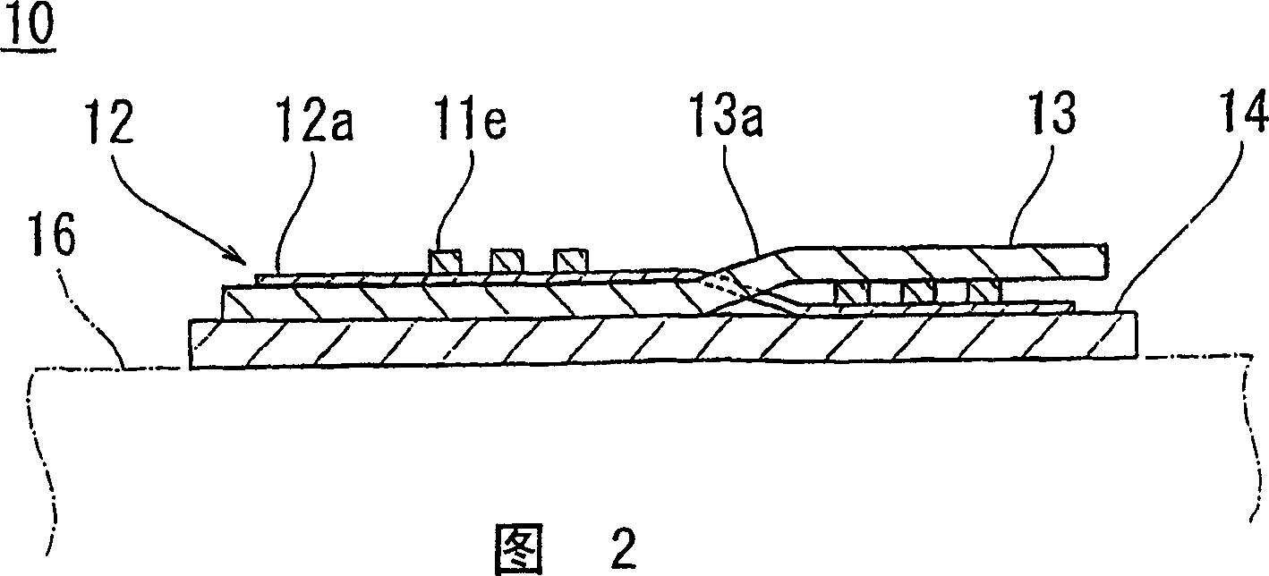
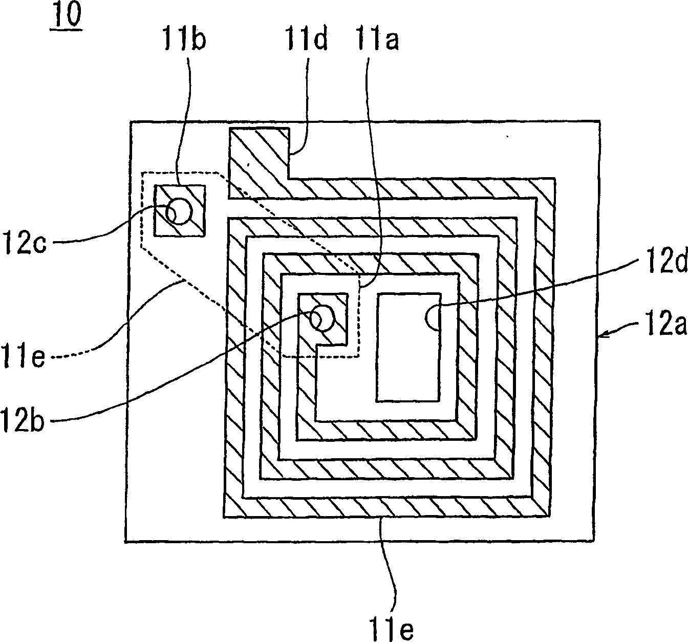
[0122]First, an air-core coil is formed on one main surface of an electrical insulating film. As the electrical insulating film, a polyimide film having a thickness of 50 μm and a length and width of 50 mm was used. Copper foils with a thickness of 35 μm are stacked on one main surface of the polyimide film, and these copper foils are etched to form a rectangular spiral wound four times on the other main surface of the polyimide film. hollow coil. The conductor constituting this air-core coil was formed with a width of 0.8 mm. The outer shape of the air-core coil formed from this conductor is 18 mm x 47 mm.

[0123] Secondly, by injection molding the mixture obtained after mixing 92% by weight of carboxyl iron powder and nylon resin, a magnetic core part 13 composed of a composite material with a thickness of 0.87 mm and an outer shape of 35 mm × 52 mm is obtained. A hole of 35 mm x 1 mm was opened in the electrical insulating film, and the magnetic core member 13 was inser...

experiment example 2

[0125] On the same electrical insulating film as in Experimental Example 1, the same air-core coil having the same conductor configuration as in Experimental Example was formed by the same steps as in Experimental Example 1. Separately, another paint obtained by mixing amorphous flakes, acrylic resin, and ethyl acetate as a solvent in a weight ratio of 70:10:20 was prepared. This paint was applied and dried to the entire surface of one main surface of a polyethylene terephthalate film having a thickness of 0.1 mm to obtain a magnetic coating film having a thickness of 0.1 mm. The film with the magnetic coating film formed on the main surface was cut into a size of 35 mm x 60 mm together with the magnetic coating film to obtain a magnetic core member 13 composed of a magnetic film coated with a composite material and dried. Next, a hole of 35 mm x 1 mm was opened in the electrical insulating film at the center of the air-core coil, and the magnetic core member 13 was inserted i...

experiment example 3

[0156] exist Figure 4 and Figure 5 An electrical conductor 112 is formed on the surface of an insulating member 111 composed of an electrical insulating film as shown. As the electrical insulating film, a polyimide film having a thickness of 50 μm and a length and width of 65 mm×55 mm was used. Copper foils with a thickness of 35 μm are laminated and bonded to one main surface of the polyimide film, and these copper foils are etched to meander on the other main surface of the polyimide film, and three pieces are alternately formed. The forward path portion 112 a and the return path portion 112 b each having a length of 40 mm are formed at a gap of 10 mm, thereby forming a series of conductors 112 . The conductor 112 is formed with a width of 0.8 mm.

[0157] Thereafter, the first magnetic core member 113 having a thickness of 1 mm and a length and width of 40 mm×20 mm was bonded to the back surface of the electrical insulating film 112 provided with the conductor 112 . T...


PUM


Abstract

An antenna coil 10 comprises an air-core coil 12 which is wound helically in a plane and a plate magnetic core member 13 which is inserted in the air-core coil 12 so as to be approximately parallel with a plane of the air-core coil 12. The magnetic core member 13 is formed by a soft magnetic metal, an amorphous or ferrite, or a composite member of a powder, flake and plastic, or rubber. The magnetic core member 13 is formed by performing an injection molding operation or a compressing molding operation of the composite member. Alternatively, the magnetic core member 13 is a magnetic coating which is formed by applying and drying the composite member. A non-magnetic conductive plate 14 which has a conductivity is layered on a surface of the air-core coil 12 through which the magnetic core member 13 is inserted. The conductive plate 14 is made of a copper, a copper alloy, an aluminum or an aluminum alloy having 0.01 to 2 mm thickness. By doing this, it is operated by relatively high frequency while it is rigid relatively.

Description

technical field [0001] The present invention relates to an antenna coil used for an identification tag using RFID (Radio Frequency Identification) technology or EAS (Electronic Article Surveillance) technology. [0002] In addition, the present invention relates to a tag using EAS (Electronic Article Surveillance) technology, or a transponder antenna for a reader / writer device or the like. More specifically, the present invention relates to an antenna for a transponder that has a helical coil and is attached to an article. Background technique [0003] Conventionally, tags using RFID technology or EAS technology are known as identification tags in which information is stored in an IC chip in an antenna coil or in which capacitors for resonance are electrically connected. The known structure of this identification tag is to activate the tag by sending radio waves of a given frequency from the transceiver antenna of the interrogator to the antenna coil, read it out by means o...

Claims


Application Information

Patent Timeline
Patent Type & Authority Applications(China)
IPC IPC(8): H01Q7/06H01Q1/38B42D15/10G06K19/00G08B13/24G06K19/07G06K19/077H01Q1/22H01Q7/00H01Q9/27H01Q11/04
CPCH01Q9/27H01Q7/00G06K19/0726H01Q1/22H01Q1/2225G06K19/07783H01Q7/06H01Q1/38G06K19/07749G06K19/07779
Inventor 远藤贵则八幡诚朗土田隆米泽政
Owner MITSUBISHI MATERIALS CORP
Why Eureka
Try Eureka