
Laser encoder, displacement measurement method of using the laser encoder, and fabricating method of numerically controlled machine

A technology for encoders and laser light sources, which is applied in the direction of transmitting sensing components, measuring devices, instruments, etc. by using optical devices, and can solve problems such as failure to reach and lower resolution of devices

Active Publication Date: 2006-12-06
SIEMENS NUMERICAL CONTROL
View PDF2 Cites 16 Cited by
  • Summary
  • Abstract
  • Description
  • Claims
  • Application Information

AI Technical Summary

Problems solved by technology

In order to avoid this abnormal beating, the distance between the scale areas on the inner and outer sides of the code disc can only be increased, which will inevitably reduce the resolution of the device and fail to reach the desired level of 1.5 μm

Method used


Image

  • Laser encoder, displacement measurement method of using the laser encoder, and fabricating method of numerically controlled machine
  • Laser encoder, displacement measurement method of using the laser encoder, and fabricating method of numerically controlled machine
  • Laser encoder, displacement measurement method of using the laser encoder, and fabricating method of numerically controlled machine

Examples


Embodiment Construction

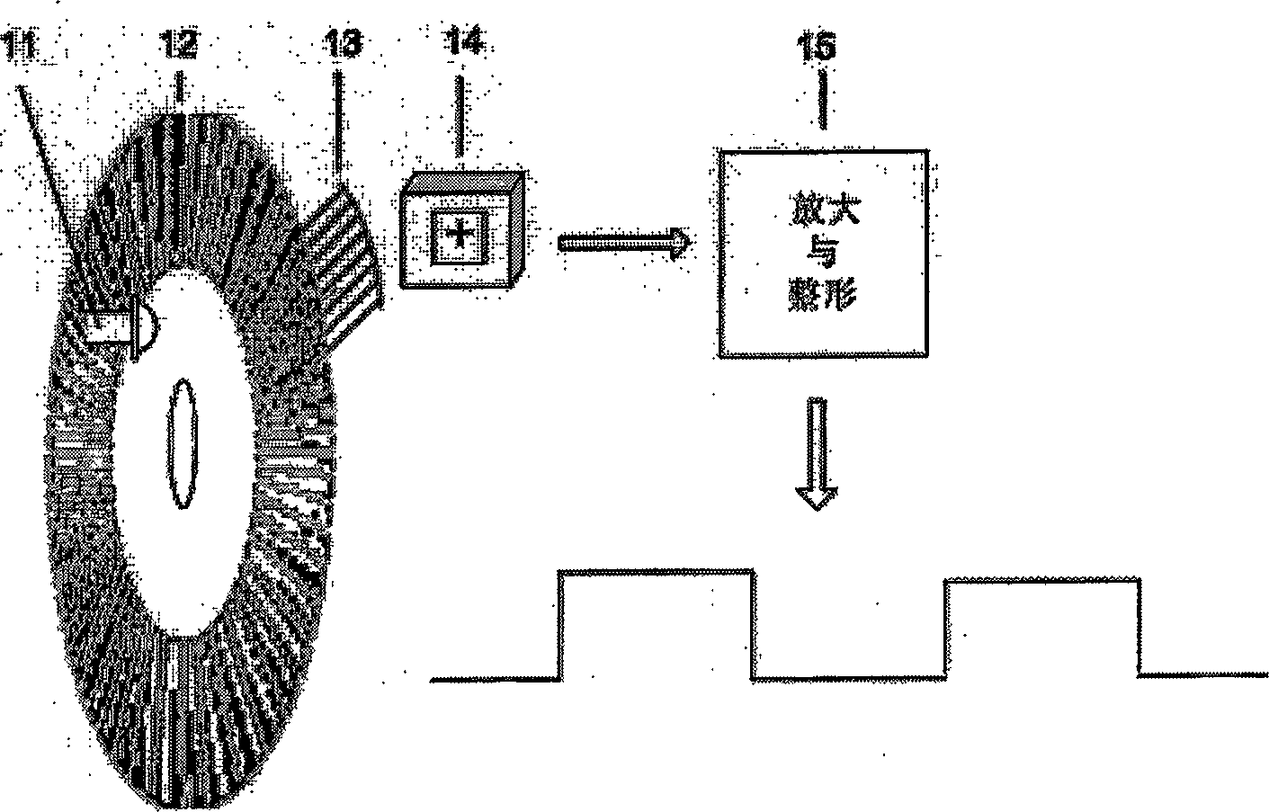
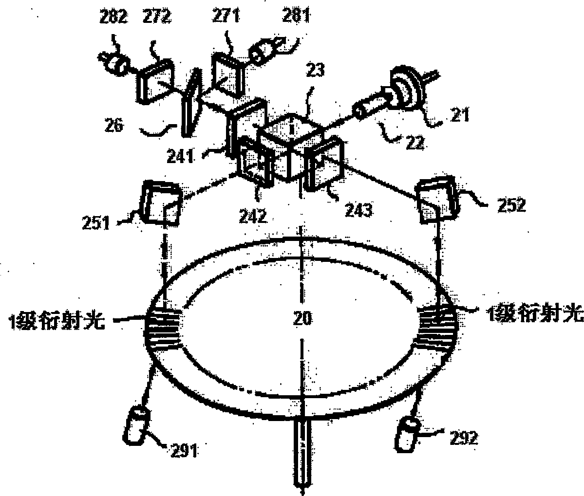
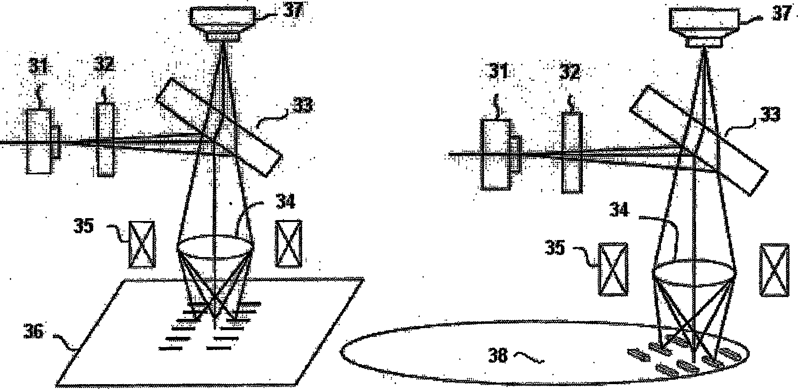
[0077] Figure 1 to Figure 3 Accordingly, some aspects of the background technology of the present invention are introduced; Figure 4 to Figure 11 Various aspects of the devices and methods of the present invention are presented.

[0078] Figure 4 The optical path of the laser encoder of the present invention is shown. In the figure, numeral 1 denotes a laser light source, 2 denotes a diffraction grating, 3 denotes a polarization beam splitter, 4 denotes a collimator lens, 5 denotes a 1 / 4 wave plate, 6 denotes an objective lens, and 7 denotes a code disk , 8 represents a concave lens, 9 represents a cylindrical lens, 10 represents a photodiode array, 7A represents a tracking coil, and 7B represents a focusing coil. As shown in the figure, the light from the diffraction grating (2) is focused on the code disc 7 after passing through the polarization splitter prism 3, the collimating lens 4, the 1 / 4 wave plate 5 and the objective lens 6, and is reflected from the code disc ...


PUM


Abstract

The invention discloses a laser coder. It includes one laser source, diffraction grating, polarization beam splitter prism, collimating lens, 1 / 4 wave plate, objective lens, coding disc, concave lens, cylindrical lens, and photo electricity receiver. The coding disc can rotate around center fixed rotating shaft. And its surface is the laser reflecting surface, and set three sets of information rail which is made up of banded unit. The invention also discloses the laser coder displacement measuring method and digital controlled machine tool processing method.

Description

(1) Technical field [0001] The invention relates to a measuring device for accurately measuring angular displacement, in particular to an incremental laser encoder based on compact disc (CD) technology, which can be applied to CNC machine tools, servo motors, various industrial machinery and other various field of automation control. (2) Background technology [0002] In servo motor and numerical control machining technology, it is necessary to accurately measure the rotation angle of a rotating shaft, so that the driven equipment driven by the rotating shaft produces a linear displacement or an angular displacement corresponding to the angle. Therefore, the more precisely the rotation angle is measured, the higher the testing and / or processing precision of the related equipment is. [0003] Incremental photoelectric encoders are widely used in various occasions. A typical incremental photoelectric encoder usually includes the following five components: light source, code ...

Claims


Application Information

Patent Timeline
IPC IPC(8): G01D5/26G01D5/347G01D5/38
CPCG01D5/34707G01D5/38G01D5/34715G01D5/36
Inventor 王广玉何明晰孟尔平曼弗雷德·勃姆
Owner SIEMENS NUMERICAL CONTROL
Learn More