Digitized liquid level measuring method using laser conduction

A liquid level measurement and digital quantification technology, applied in liquid/fluid solid measurement, measurement device, liquid level indicator, etc., can solve the problems of reducing measurement delay, inappropriate automatic signal adjustment, etc., to reduce measurement delay and wide range of applications , the effect of simple structure

Inactive Publication Date: 2006-12-13
田逸
View PDF0 Cites 7 Cited by
  • Summary
  • Abstract
  • Description
  • Claims
  • Application Information

AI Technical Summary

Problems solved by technology

The characteristics are: digital signal output, convenient for remote transmission, avoiding the use of pressure guide tubes, reducing the measurement delay, no variation and scale errors caused by mechanical transmission, and simplifying the maintenance and adjustment of the instrument, but there is a large distance between electrodes Signal dead zone between electrodes, not suitable for automatic adjustment signal

Method used


Image

  • Digitized liquid level measuring method using laser conduction
  • Digitized liquid level measuring method using laser conduction
  • Digitized liquid level measuring method using laser conduction

Examples


Embodiment 1

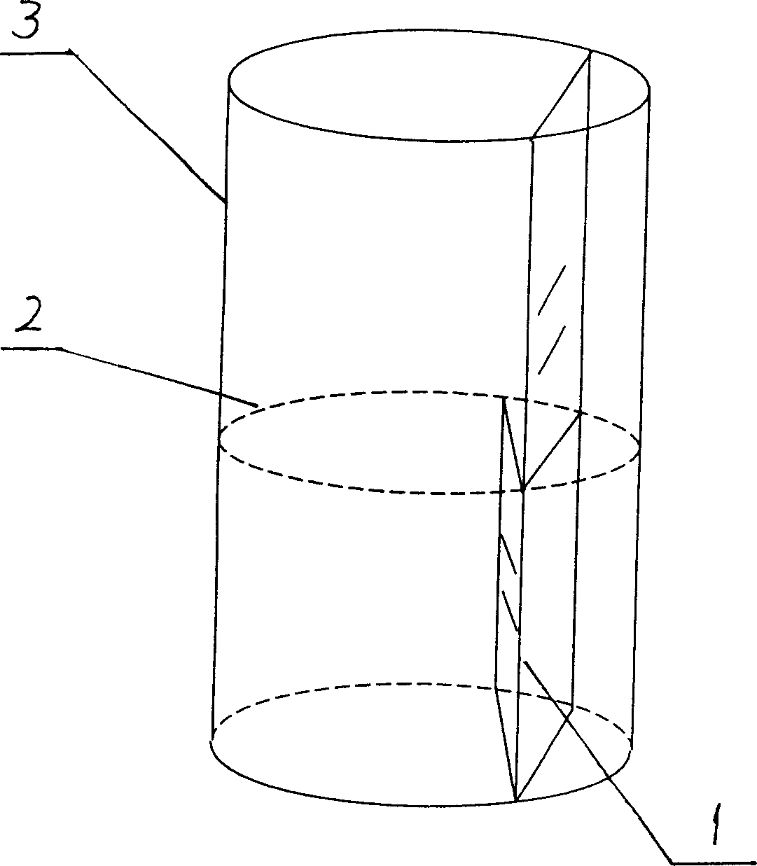
[0026] Example 1, see figure 1 , when the laser beam passes through the transparent liquid 2 of the cylindrical tubular connector, and the incident path 1 of the laser beam does not pass through the axis of the cylindrical tubular connector 3, the light will be horizontally deflected, and the degree of deflection varies with the incidence of the laser beam The distance between path 1 and the axis of the cylindrical tube changes. This is the main theoretical basis of the present invention.

[0027] According to this principle, the liquid level measuring method of the present invention is made up of the following steps:

Embodiment 2

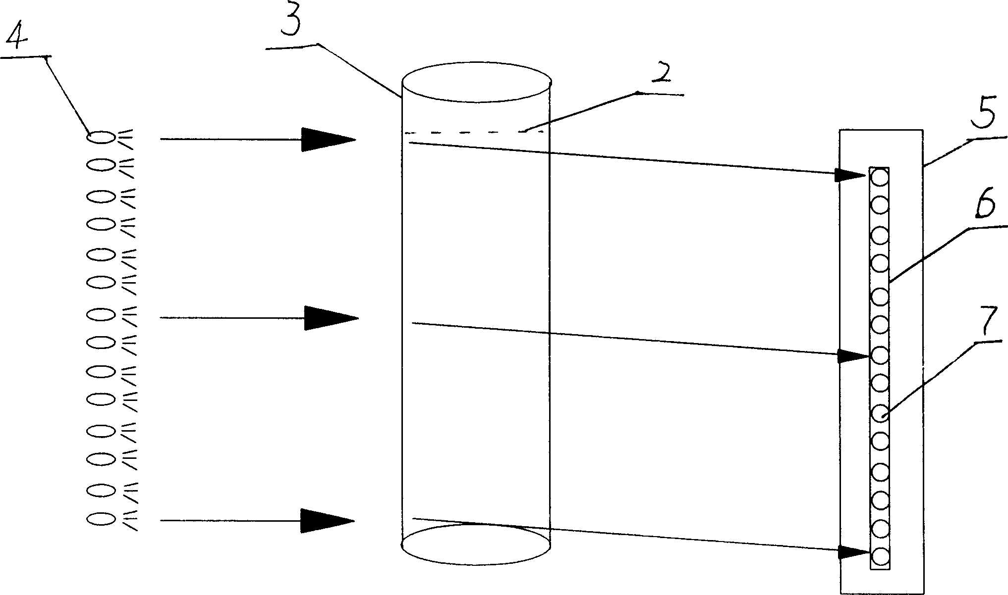
[0028] In embodiment 2, the position of the light bar is used to determine the liquid level. The specific measurement method is: see figure 2 , using a cylindrical tubular transparent (such as glass, or quartz, etc.) connecting sampler 3. Outside the cylindrical tubular transparent connected sampler 3, a row of laser light-emitting tubes (such as laser diodes) is installed along its axial direction as the laser source for short as the laser tube row 4. see figure 2 , image 3 , the height of the laser tube row 4 is equal to the measuring range H of the liquid level 2. In this way, a row of laser beams can pass through the cylindrical tubular transparent connected sampler 3. Note: the path of the laser beam row 4 incident on the cylindrical tubular transparent connected sampler 3 cannot pass through its axis.

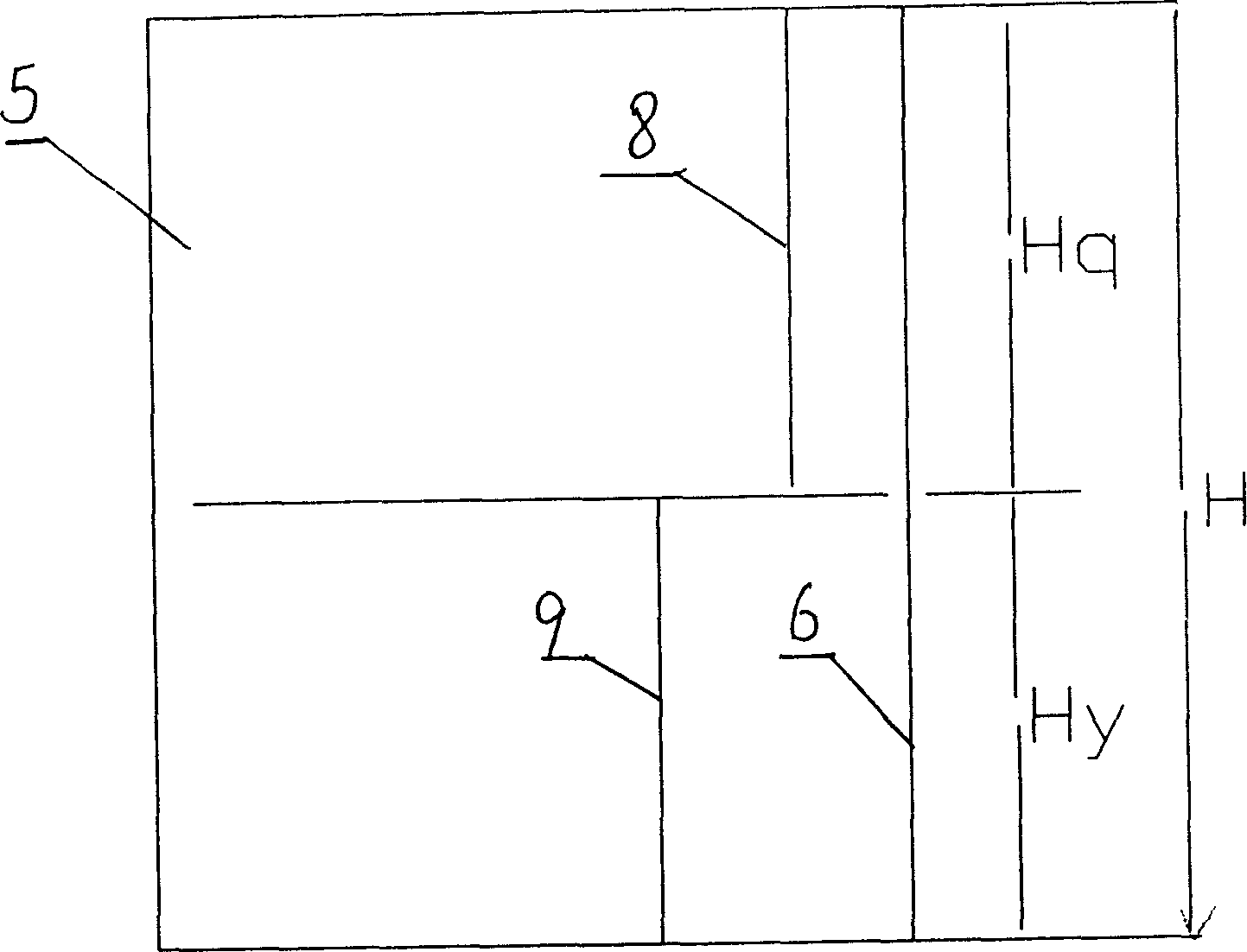
[0029] see figure 2 A background surface 5 with a scale is set on the opposite side of the cylindrical tubular transparent connected sampler 3, and the light emi...

Embodiment 3

[0032] Embodiment 3, using the position of the photosensitive tube to determine the liquid level. see figure 2 , the specific method is: install a row of photosensitive tubes (photosensitive diodes, or photosensitive triodes, etc.) for receiving laser beams at the position of light strip 8 on the liquid surface or light strip 9 under the liquid surface to form a photosensitive tube row 7, and the photosensitive tubes The height of the row 7 is equal to the span H for measuring the liquid level 2 . Opposite to laser tube row 4. If the photosensitive tube row 7 is installed at the position of the light bar 9 under the liquid surface, the photosensitive tubes receiving the laser light are activated, and the positions of these activated photosensitive tubes represent the actual liquid level. If the photosensitive receiving tube row 7 is installed at the "light bar on the liquid surface" position, then on this photosensitive tube row, the positions of the photosensitive tubes th...


PUM


Abstract

Disclosed is a method for measuring laser conductive and digital quantizing liquid level. The method comprises setting laser diodes array along the axial of a cylindrical transparent connecting vessels, wherein the height of the laser diodes array is greater than the measuring range of the liquid level to be measured; setting a background on the opposite position of the cylindrical transparent connecting sampler to make the laser light beam emitted from the laser diodes array project on the background and form a vertical light striation, and defining the height of the liquid level according to the height of the light striation; setting photosensitive tubes array on the site of the light striation for receiving laser beam, wherein the height of the photosensitive tubes array corresponds to the laser diodes array and equals the measuring range of the liquid level to be tested, and the situation shown by the photosensitive tubes represents the real height of the liquid level.

Description

technical field [0001] The invention relates to a quantitative and digital liquid level measurement method using laser refraction, photoelectric induction, and synchronization, and belongs to the technical field of industrial liquid level measuring instruments, in particular to a laser conduction, digital liquid level measurement method. Background technique [0002] At present, industrial liquid level measurement, especially industrial boiler water level measurement, mainly uses the following three water level gauges for measurement: mica water level gauge, differential pressure water level gauge, and electric contact water level gauge. [0003] Measuring principles, characteristics and defects of three water level gauges: [0004] The mica water level gauge uses the static balance principle of the connector to measure the water level. It is characterized by simple structure, intuitive and reliable reading, and is the most reliable instrument for monitoring the water level...

Claims


Application Information

Patent Timeline
Patent Type & Authority Applications(China)
IPC IPC(8): G01F23/292
Inventor 田逸田宝宏
Owner 田逸
Why Eureka
Try Eureka