Light transmission/reception module and light transmission/reception device

An optical transceiver and transceiver technology, applied in electromagnetic transceivers, lasers, phonon exciters, etc., can solve problems such as increased electrical crosstalk

Inactive Publication Date: 2007-01-24
PANASONIC CORP
View PDF2 Cites 21 Cited by
  • Summary
  • Abstract
  • Description
  • Claims
  • Application Information

AI Technical Summary

Problems solved by technology

That is, if to improve the high-frequency characteristics of optical reception such as Figure 11 As shown in the optical transceiver module 100 of the related art (described in JP-A-2001-345475), the capacitor C is added to the cathode terminal of the photodetector 107, then the electrical crosstalk will also increase

Method used


Image

  • Light transmission/reception module and light transmission/reception device
  • Light transmission/reception module and light transmission/reception device
  • Light transmission/reception module and light transmission/reception device

Examples


no. 1 example

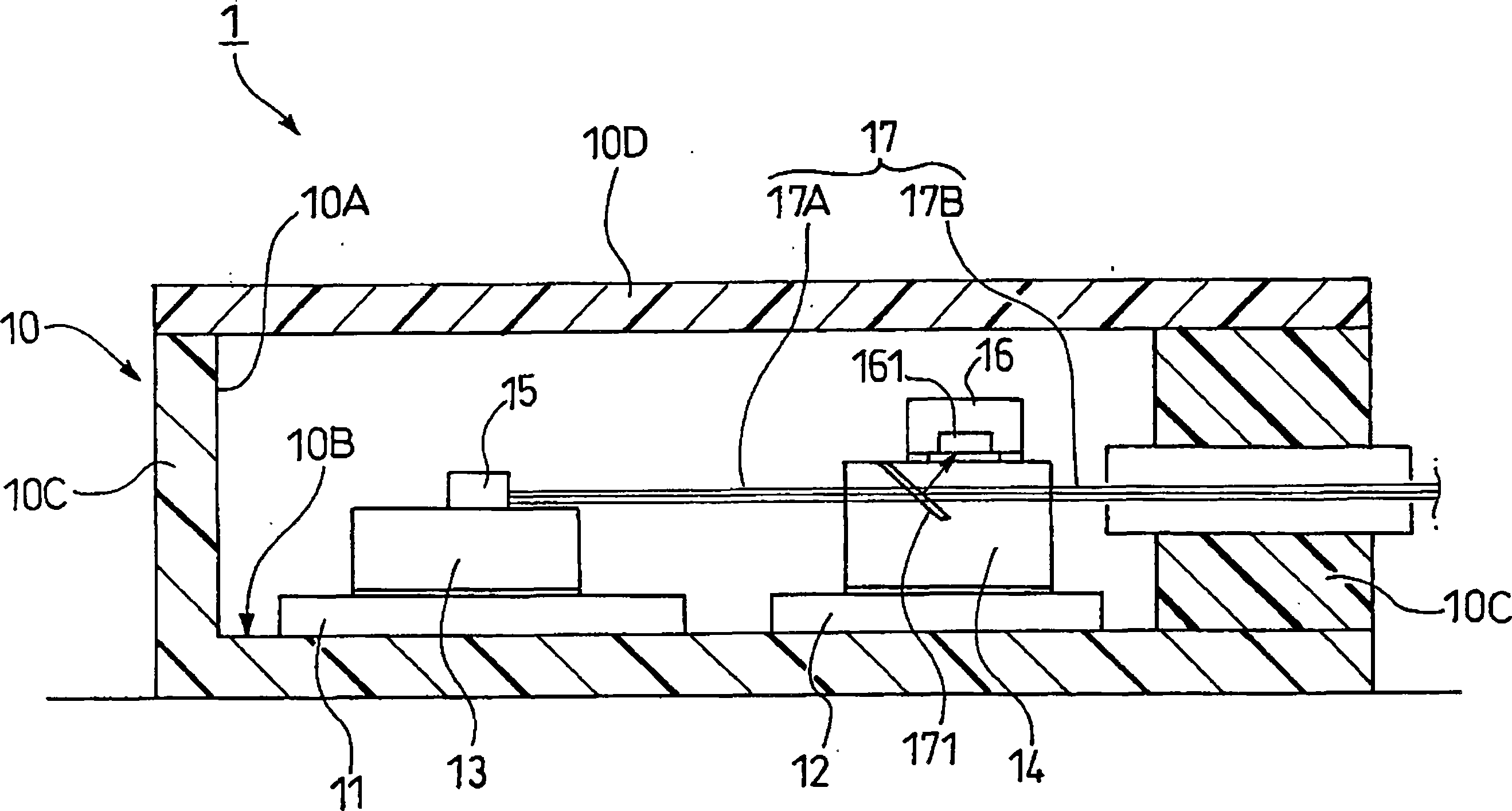
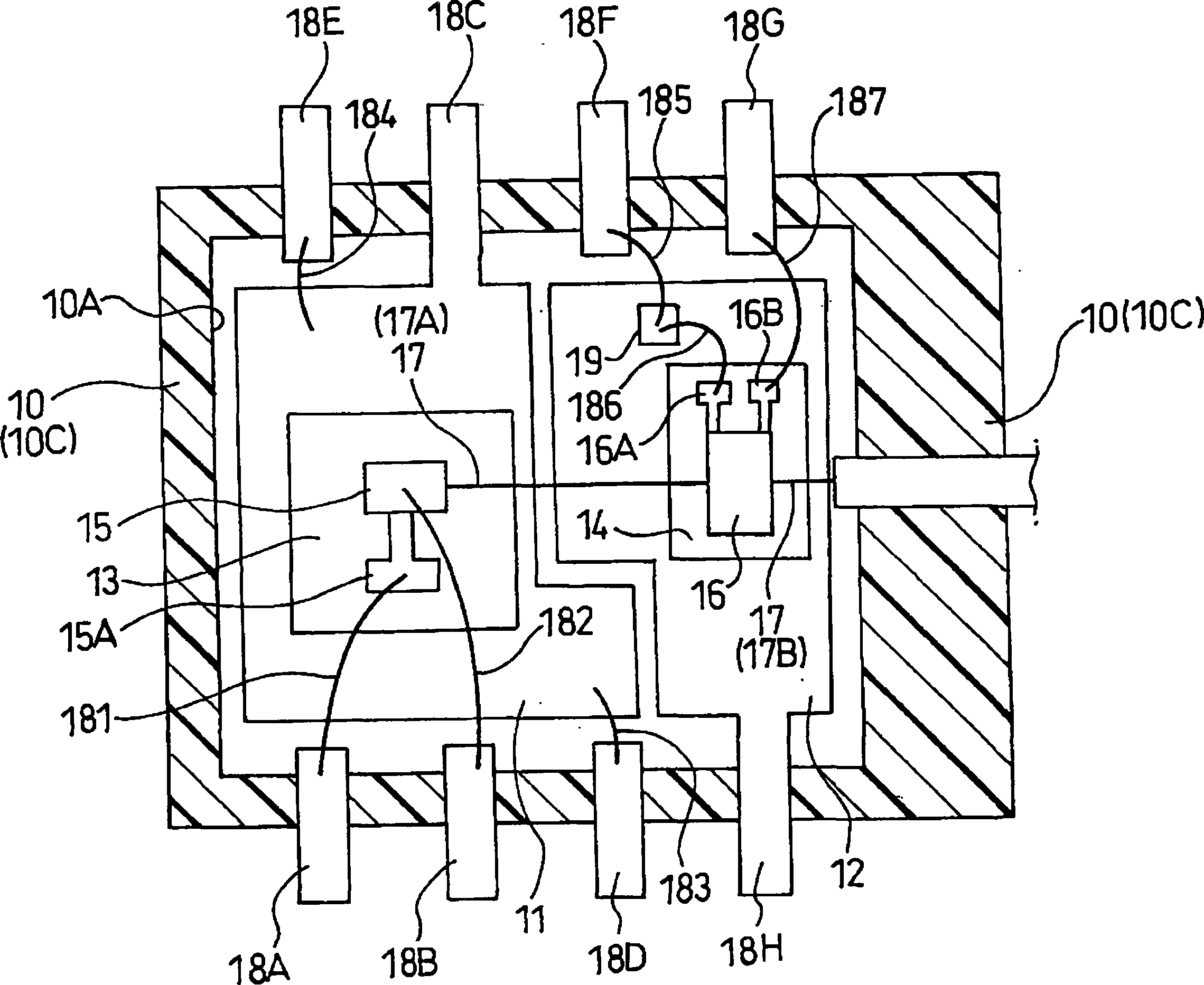
[0063] figure 1 and figure 2 The configuration of the optical transceiver module according to the first embodiment of the present invention is shown. The optical transceiver module includes inside the package 10: a first metal plate 11 and a second metal plate 12 provided separately and independently of each other, a first substrate 13 and a second substrate 14 respectively provided on the metal plate , a light emitting device 15 mounted on the first substrate 13 , a photodetector 16 mounted on the second substrate 14 , an optical waveguide 17 , leads 18 and a capacitor 19 .

[0064] In order to reduce the overall cost, the package 10 is a resin package formed of a suitable resin material into a substantially box shape with a bottom.

[0065] The package 10 includes a removable cover 10D to add strength and protect the optics and electrical devices inside. In order to increase the strength of the package, the cover 10D may be formed of the same resin material as that of t...

no. 2 example

[0111] Next, refer to Figure 6 A second embodiment of the present invention is described. Components in this embodiment that are the same as in the first embodiment are denoted by the same symbols, and repeated descriptions are omitted.

[0112] Figure 6The configuration of the optical transceiver module 2 according to the second embodiment of the present invention is shown. The optical transceiver module 2 has the same configuration as the optical transceiver module 1 according to the first embodiment except that a preamplifier 21 and a second capacitor 22 are additionally mounted on the second metal plate 12 .

[0113] A preamplifier 21 is used to increase the amplification. Electrical connection is established between a terminal (not shown) of the preamplifier 21 for connecting the cathode of the photodetector 16 and the cathode terminal of the photodetector 16 via the sixth bonding wire 186 and the eighth bonding wire 231 . An electrical connection is established bet...

no. 3 example

[0118] Next, refer to Figure 6 A third embodiment of the present invention is described. The same components in this embodiment and the first embodiment are represented by the same symbols, and repeated descriptions are omitted.

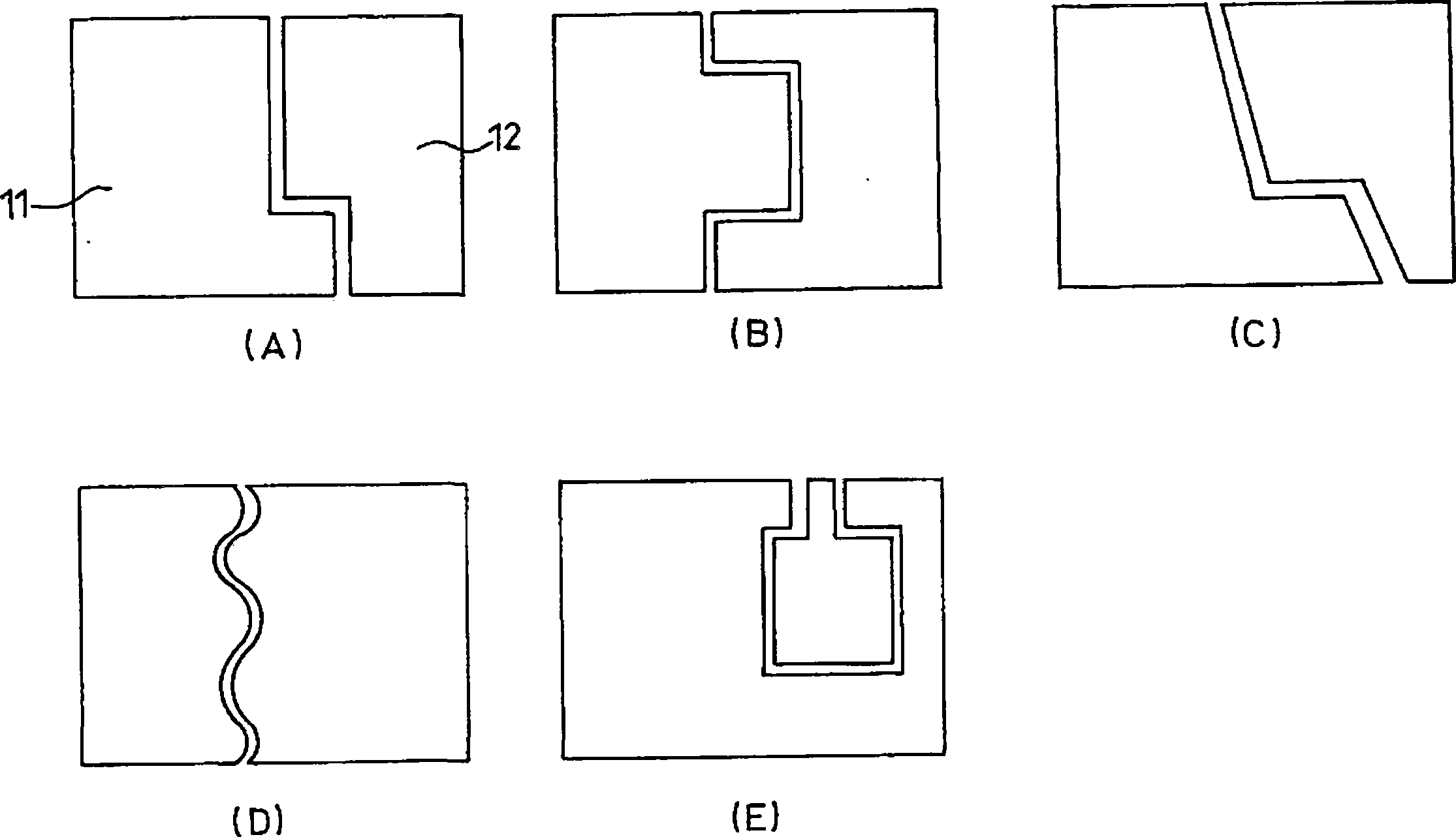
[0119] Figure 7 The configuration of the optical transceiver module 3 according to the third embodiment of the present invention is shown. The optical transceiver module 3 of the third embodiment has the same configuration as the optical transceiver module 1 according to the first embodiment, except that the former further includes a through hole on the bottom surface of the first metal plate 11 penetrating the bottom plate 10E of the package 10. The hole 10F, the metal 11A for conductive external connection provided at the through hole 10F, the through hole 10G penetrating the bottom plate 10E of the package 10 on the bottom surface of the second metal plate 12, and the conductive external connection provided at the through hole 10G. Metal 12A....


PUM


Abstract

Providing an optical transceiver module that reduces electric crosstalk between a light emitting device and a photodetector while providing an excellent high-frequency characteristic, and an optical transceiver including the same. According to the invention, a first metal plate having a first substrate for mounting a light emitting device and a at second metal plate having a second substrate for mounting a photodetector are provided separately and independently of each other in a resin package, thus reducing the parasitic capacitance. This provides an optical transceiver module capable of suppressing electric crosstalk where part of a high-frequency signal causes a variation in the potential at a terminal of a photodetector while improving the high frequency characteristic in driving the light emitting device with a high-frequency signal, and an optical transceiver including the same.

Description

technical field [0001] The present invention relates to an optical transceiver module in which a light emitting device and a photodetector are installed in the same module for bidirectional transmission, and an optical transceiver including the optical transceiver module, and particularly relates to reducing the number of light emitting devices and photodetectors. An optical transceiver module that provides excellent high-frequency characteristics while providing electrical interference between them, and an optical transceiver including the optical transceiver module. Background technique [0002] Recently, as Internet communication speeds up, an optical communication system called FTTH (Fiber To The Home) is widely used in trunk line communication systems and subscriber line communication systems. In this optical communication system, a method is used in which a single optical fiber cable is used to transmit optical signals having different wavelengths for upstream and down...

Claims


Application Information

Patent Timeline
Patent Type & Authority Applications(China)
IPC IPC(8): H01L31/02H01S5/022H01L31/0232H01L31/167H01L33/48H01L33/62H01S5/02
CPCH01S5/02216H01L2224/48091H01S5/02248H04B10/40H01S5/02284H01S5/06226H01L2224/48247H01L2224/45124H01L2224/45144H01L31/167H01L2224/48145H01L2924/30107H01L2224/4911H01S5/02251H01S5/02325H01L2924/00014H01L2924/00H01L2924/00012
Inventor 野嶋一宏古泽佐登志西川透浅野弘明
Owner PANASONIC CORP
Why Eureka
Try Eureka