

Method and apparatus for generating ozone
An ozone generating device and ozone technology, applied in the ozone generating device with synergistic effect of discharge and catalyst, in the field of ozone generation, to achieve the effect of improving ozone generation efficiency and reaction rate
- Summary
- Abstract
- Description
- Claims
- Application Information
AI Technical Summary
Problems solved by technology
Method used
Image

Examples
Embodiment 1
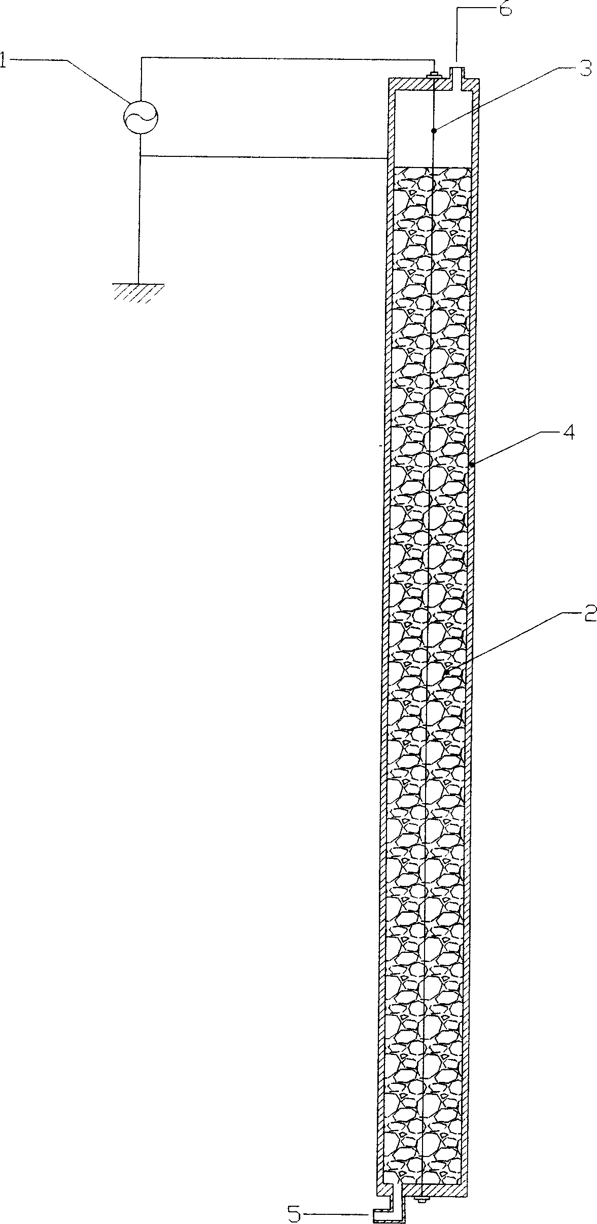
[0034] figure 1 A cross-sectional view of the ozone generator according to Embodiment 1 of the present invention is shown. It includes: a high-voltage power supply 1, a catalyst 2, a high-voltage electrode 3, a grounding electrode 4, a feed gas inlet 5, and an ozonated gas outlet 6. The device is an ozone generating device composed of a wire-shaped metal high-voltage electrode and a cylindrical metal grounding electrode. In this embodiment, the metal pipe serves as the ground electrode 4 and is connected to the ground electrode of the high voltage power supply 1 , the metal wire is at the axial center of the cylindrical ground electrode 4 , and the high voltage electrode 3 is connected to the high voltage stage of the high voltage power supply 1 . The diameter of the high-voltage electrode wire is 0.5 mm, and the inner diameter of the ground electrode metal tube is 25 mm. The two ends of the metal tube grounding electrode 4 are closed with an insulating cover with openings f...
Embodiment 2
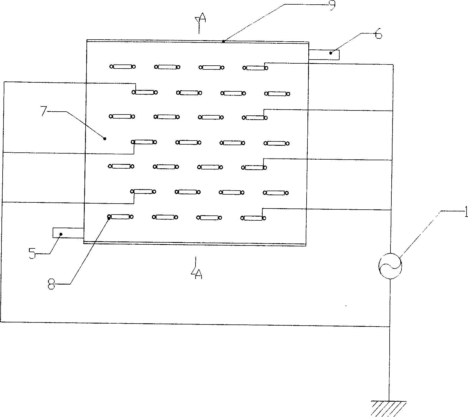
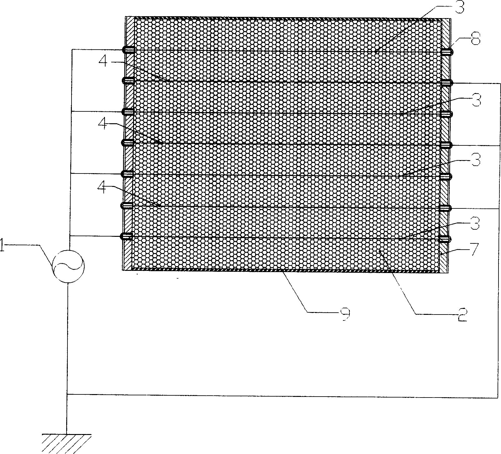
[0037] figure 2 , image 3 The main part of the ozone generator according to Embodiment 4 of the present invention is shown. It includes: high-voltage power supply 1, catalyst 2, high-voltage electrode 3, grounding electrode 4, feed gas inlet 5, ozonation gas outlet 6, metal wire integrated board 7, metal hollow tube 8, and seal 9. The device is an ozone generating device in which both the high-voltage electrode 3 and the ground electrode 4 are made of wire-like metal. In this embodiment, several wire-shaped metal electrodes are arranged in parallel in a rectangular closed box, that is, several rows and columns of wire-shaped metals are distributed in parallel in the area of the box, and the wire-shaped metal electrodes arranged in rows are arranged in the box. Several parallel planes are formed, and each plane contains the same number of metal wires arranged in parallel. The wire diameter is 0.5mm. The metal wires in each plane are connected in series, and the metal wi...
Embodiment 3
[0039] Figure 4 , Figure 5 The main part of the ozone generator according to Embodiment 3 of the present invention is shown. It includes: high-voltage power source 1, catalyst 2, high-voltage electrode 3, grounding electrode 4, feed gas inlet 5, ozonated gas outlet 6, sealing 9, quartz glass tube 10, and quartz glass outer sleeve 11. The device uses metal wire as the high voltage electrode and water as the ozone generator. In this example, the structure of the device is similar to Example 1, except that the metal tubular ground electrode in Example 1 is changed to a water electrode composed of a glass sleeve and water filling the inside of the sleeve. Water is the conductive electrode, and the wall of the glass sleeve acts as a dielectric barrier. In this embodiment, the inner diameter of the quartz glass tube 10 is 10-40 mm, and the wall thickness is 1-3 mm. Filiform metal high-voltage electrode 3 passes through quartz glass tube 10, and is fixed at the center of the tw...
PUM
| Property | Measurement | Unit |
|---|---|---|
| diameter | aaaaa | aaaaa |
| particle diameter | aaaaa | aaaaa |
| thickness | aaaaa | aaaaa |
Abstract
Description
Claims
Application Information