System and method for multiple laser triggering

A trigger and excitation light source technology, applied in the field of flow cytometry, can solve problems such as inability to calibrate the excitation light source or center rate

Inactive Publication Date: 2007-02-07
BECKMAN COULTER INC
View PDF4 Cites 11 Cited by
  • Summary
  • Abstract
  • Description
  • Claims
  • Application Information

AI Technical Summary

Problems solved by technology

[0010] Alternative solutions for temporal separation, such as the use of gated amps or delay lines, require prior knowledge of the relati

Method used


Image

  • System and method for multiple laser triggering
  • System and method for multiple laser triggering
  • System and method for multiple laser triggering

Examples


Embodiment Construction

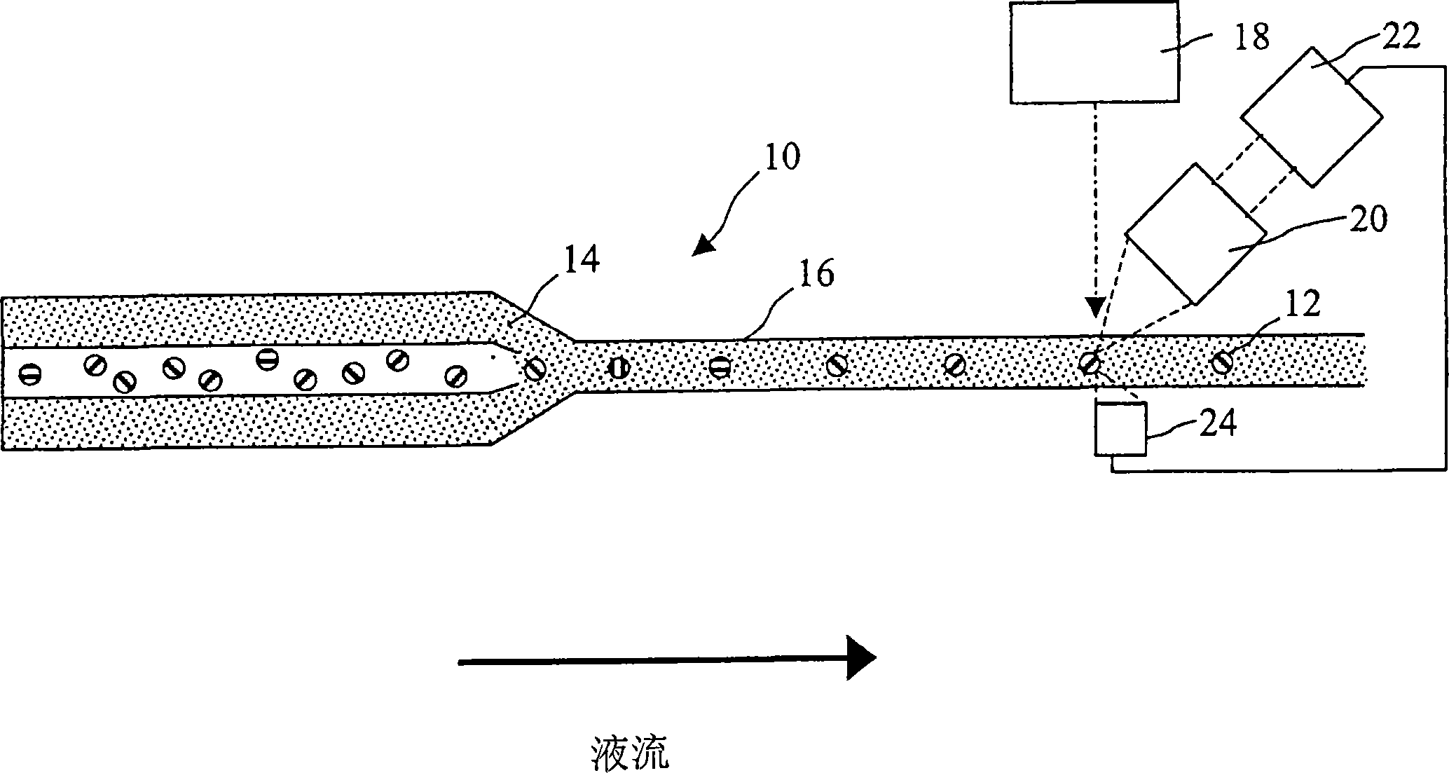
[0033] Typically, the present invention is used in conjunction with a flow cytometer. In a flow cytometer, particles are interrogated using one or more excitation light sources as they pass in a single file through a detection zone of a flow cell. The sample particles may be microspheres containing and / or coated with fluorescent indicator dyes excited by an excitation light source. Typically, the microspheres are polystyrene particles with a diameter of 0.5 to 10 μm.

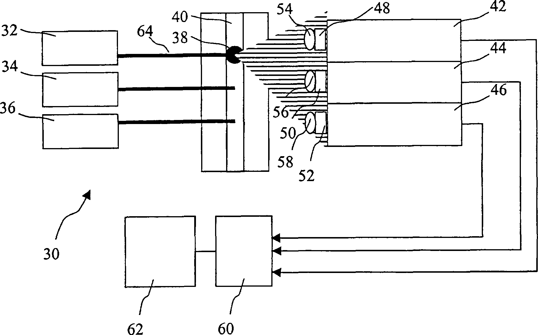
[0034] The excitation light source can be a diode laser, solid state laser, gas laser, dye laser, arc lamp, or other light source known to those skilled in the art. For example, a 532nm laser can be used to induce dyes such as phycoerythrin (PE), CY3, and DBCY3 dyes that fluoresce at about 550nm to 620nm, while a 635nm laser can be used to induce dyes such as squarine dyes and cyanine dyes at about 650nm to 750nm. Fluorescent. The present invention can include a third laser emitting at 488nm, and the inventio...


PUM


Abstract

A system for measuring the irradiance of a fluorescently labeled particle having a cytometric flow chamber; a plurality of excitation light sources; a plurality of scatter detectors, each configured to detect light from only one of the plurality of excitation light sources and arranged so as to detect scattered light from the particle; a trigger connected to the plurality of scatter detectors, the trigger emitting a signal when scattered light incident on one of the scatter detectors is exceeding a predetermined threshold value; collection optics; at least one fluorescence detector to receive emissions collected by the collection optics and generate an output, the at least one fluorescence detector being configured to respond only to a discrete number of wavelength bands; and an integrator for recording the output of the at least one fluorescence detector in response to a signal from the trigger.

Description

[0001] Cross References to Related Applications [0002] This application claims priority to US Patent Application No. 10 / 763,652, filed January 23, 2004, entitled "Multiple Laser Triggering System and Method," which is incorporated herein by reference. technical field [0003] The present invention relates to flow cytometry, and more particularly, the present invention relates to systems and methods for using multiple lasers in flow cytometry. Background technique [0004] In a typical flow cytometer 10 , as shown in FIG. 1 , a sample solution of particles 12 is mixed with a sheath fluid 14 . The particles can be fluorescently labeled and can be cells or microspheres made of polystyrene or other materials. The sheath fluid 14 flows in such a way that it hydraulically focuses the particle-containing sample solution 12 for analysis. The particle-containing sample solution 12 and the sheath fluid 14 flow along the flow channel 16 . Excitation light source 18, typically a la...

Claims


Application Information

Patent Timeline
IPC IPC(8): G01N15/14
CPCG01N15/14G01N2021/6441
Inventor 罗伯特·爱德华·奥尔克拉伦斯·卢斯特芬·L·小彭托尼杨大伟
Owner BECKMAN COULTER INC
Why Eureka
Try Eureka