An ion trap and a method for dissociating ions in an ion trap

A technology of ion traps and quadrupole ion traps, applied in the field of ion traps, can solve problems such as no experimental basis and no theoretical basis, and achieve the effect of reducing the electric field intensity

Active Publication Date: 2007-02-28
岛津欧州研究所
View PDF3 Cites 20 Cited by
  • Summary
  • Abstract
  • Description
  • Claims
  • Application Information

AI Technical Summary

Problems solved by technology

However, this expectation has neither theoretical nor experimental support

Method used


Image

  • An ion trap and a method for dissociating ions in an ion trap
  • An ion trap and a method for dissociating ions in an ion trap
  • An ion trap and a method for dissociating ions in an ion trap

Examples


Embodiment Construction

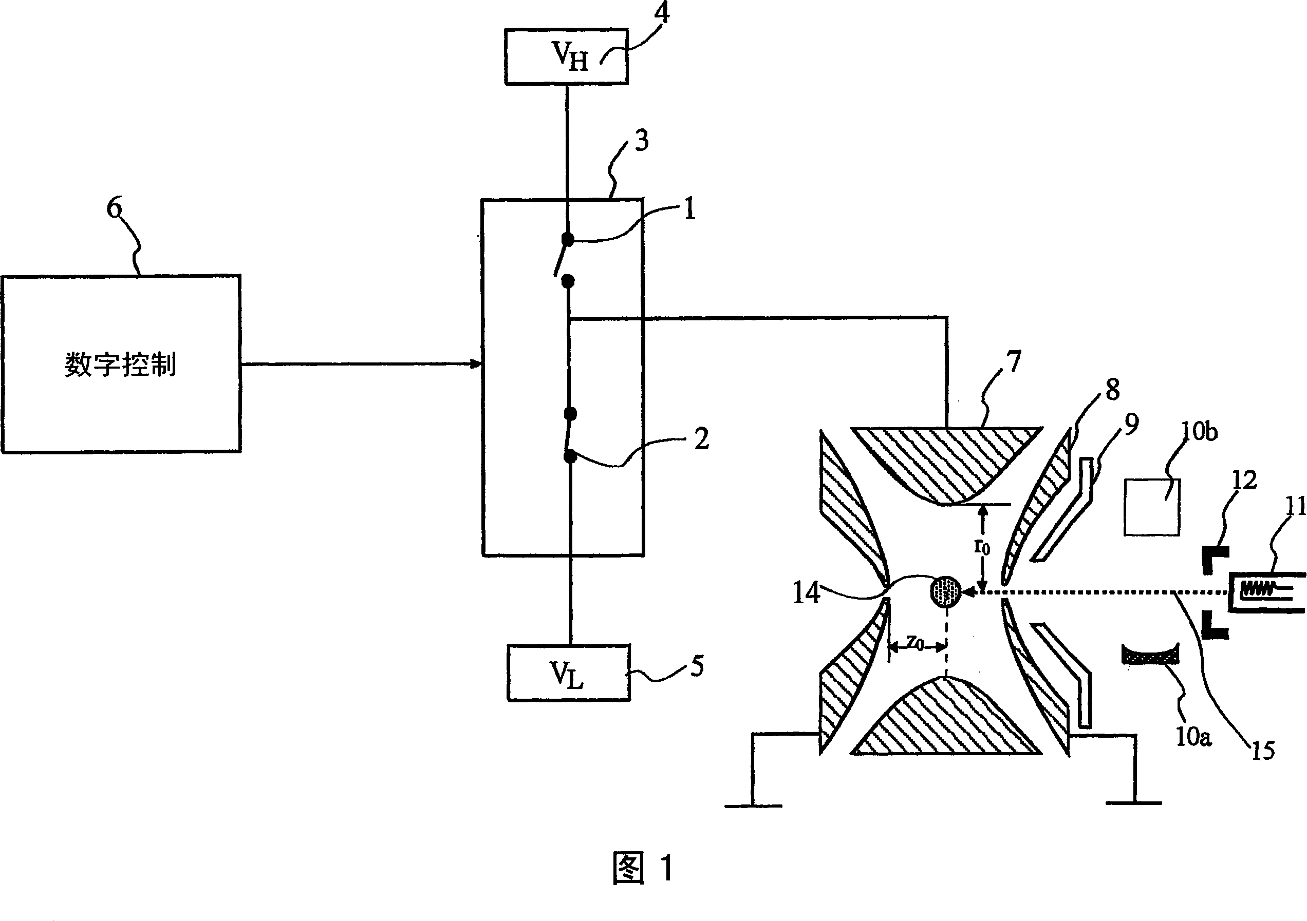
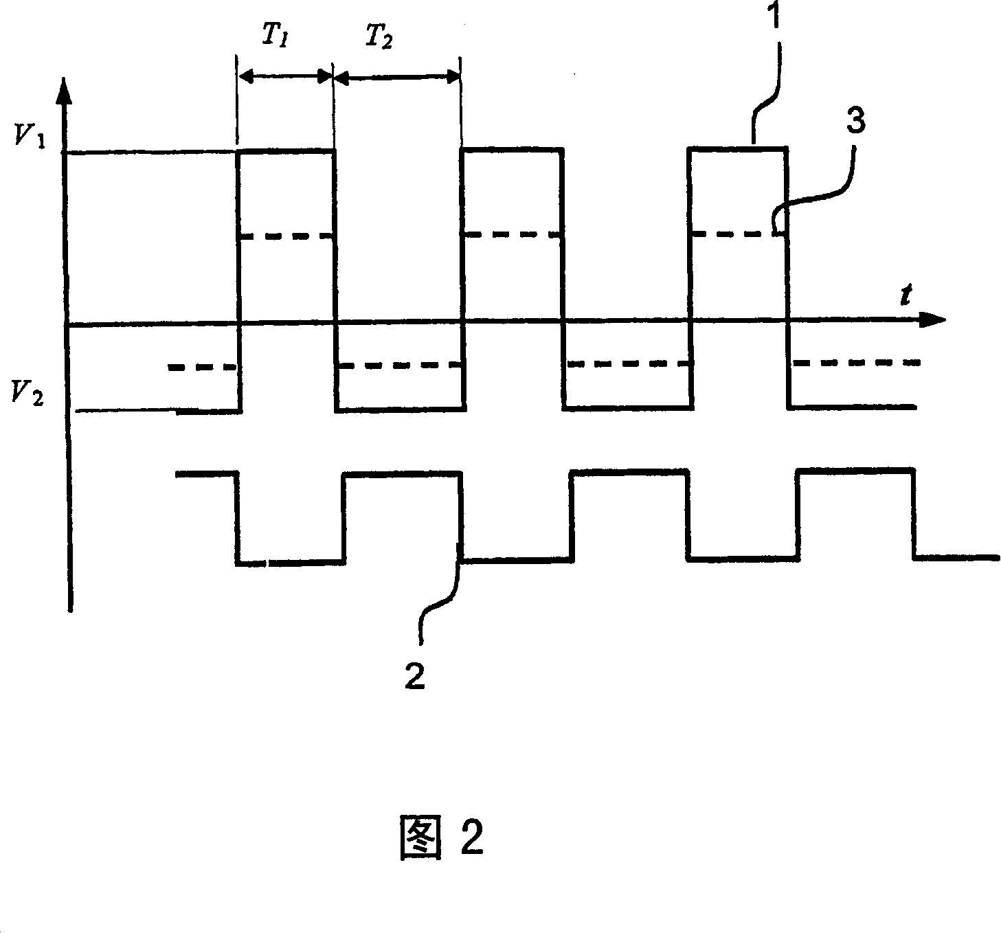
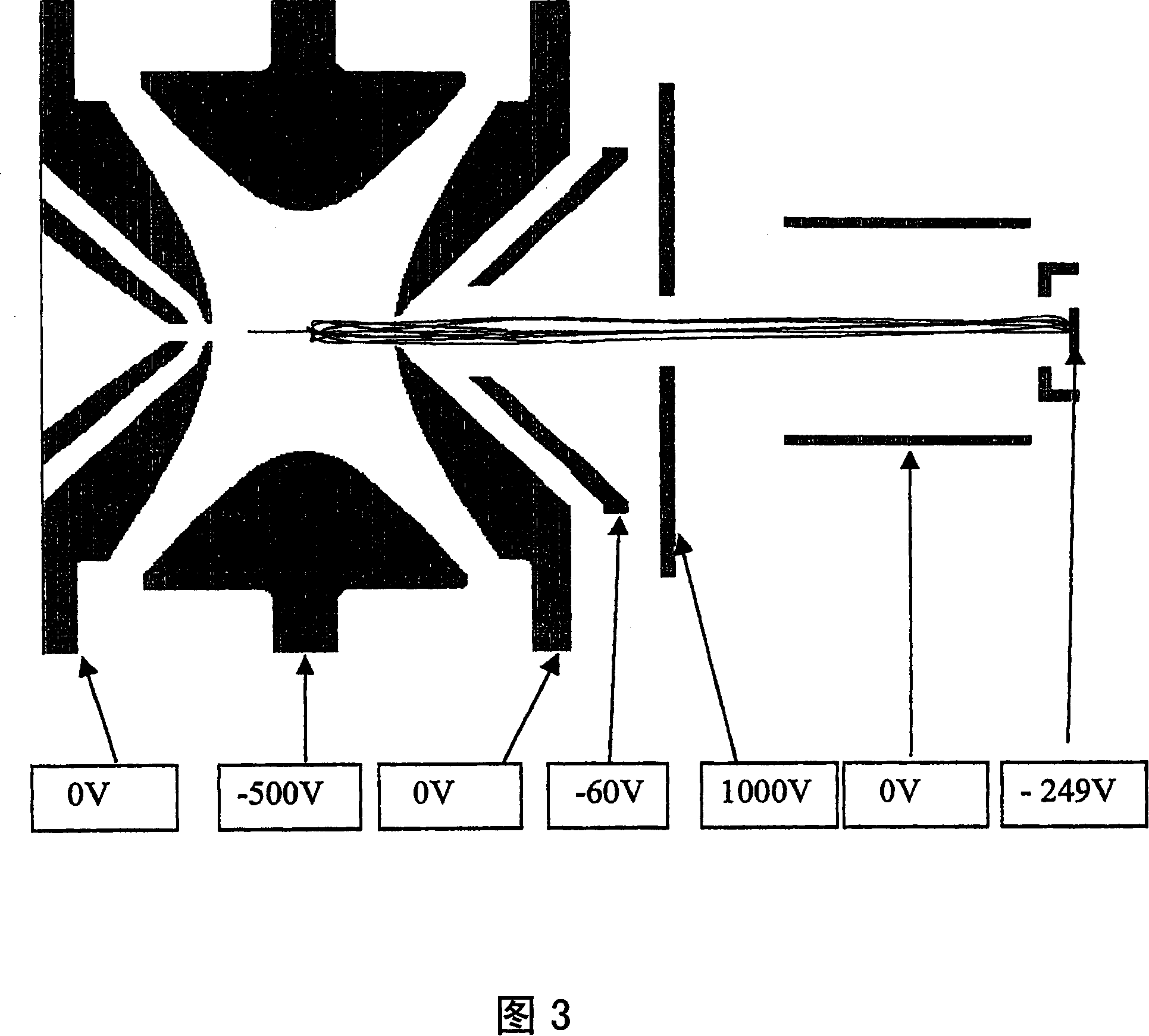
[0026] 1 of the accompanying drawings shows an embodiment of the present invention, wherein a ring electrode 7 of a 3D ion trap is connected to a pair of switches 1 and 2 . Switches 1 and 2 are electronic switches connected in series as shown in FIG. 1 . In this embodiment, switch 1 is connected to a high-level DC power source 4 , and switch 2 is connected to a low-level DC power source 5 . The switches are alternately turned on and off to generate a driving voltage of a rectangular waveform that is applied to the ring electrode 7 of the quadrupole ion trap. The quadrupole ion trap has at least one aperture in the emitter cap electrode 8 through which ions can be emitted to the off-axis detector 10 via the extraction electrode 9 . The off-axis detector 10 includes a conversion dynode 10a and an electron multiplier 10b. When the ECD process is activated, the high voltage bias on the detector 10 is switched off and the electron emitter 11 is switched on. The pulsed electron b...


PUM


Abstract

A quadrupole ion trap includes a switch (3) for switching a trapping voltage between discrete voltage levels VH, VL. This creates a digital trapping field for trapping precursor ions and product ions in a trapping region of the ion trap. A gating voltage is applied to a gate electrode (12) to control injection of source electrons into the ion trap. Application of the gating voltage is synchronised with the switching so that electrons are injected into the trapping region while the trapping voltage is at a selected one of the voltage levels and can reach the trapping region with a kinetic energy suitable for electron capture dissociation to take place.

Description

technical field [0001] The present invention relates to an ion trap and a method for dissociating ions in the ion trap, in particular to a quadrupole ion trap and to a tandem mass analysis using the quadrupole ion trap. Background technique [0002] Tandem mass analysis can be achieved by employing an ion trap analyzer, which can be in the form of a magnetic cyclotron (FTICR MS) or a high frequency quadrupole ion trap. In a tandem mass spectrometer, precursor ions with specific mass-to-charge ratios are selected and separated within a trapping volume. The dissociation process is then performed using one of several known activation methods, including collision-induced dissociation (CID), surface-induced dissociation (SID), infrared multiphoton dissociation (IRMPD), and electron capture dissociation (ECD) . The product ions produced by this process are measured using mass scanning to obtain MS 2 Spectrum. If the precursor ion is further selected from the product ion and th...

Claims


Application Information

Patent Timeline
Patent Type & Authority Applications(China)
IPC IPC(8): H01J49/40H01J49/42
CPCH01J49/0054H01J49/42
Inventor 丁力
Owner 岛津欧州研究所
Why Eureka
Try Eureka