Pipe pile hole maker with concrete bottom sealing, pipe cover and wings and construction process thereof

A technology of concrete and hole former, applied in the field of foundation engineering, can solve problems such as applicability restriction, and achieve the effects of reducing post-construction settlement, good quality and increasing strength

Active Publication Date: 2007-03-14
华北建设集团有限公司 +1
View PDF0 Cites 25 Cited by
  • Summary
  • Abstract
  • Description
  • Claims
  • Application Information

AI Technical Summary

Problems solved by technology

Due to the complexity of geological conditions, its applicability is restricted

Method used


Image

  • Pipe pile hole maker with concrete bottom sealing, pipe cover and wings and construction process thereof
  • Pipe pile hole maker with concrete bottom sealing, pipe cover and wings and construction process thereof
  • Pipe pile hole maker with concrete bottom sealing, pipe cover and wings and construction process thereof

Examples


Embodiment 1

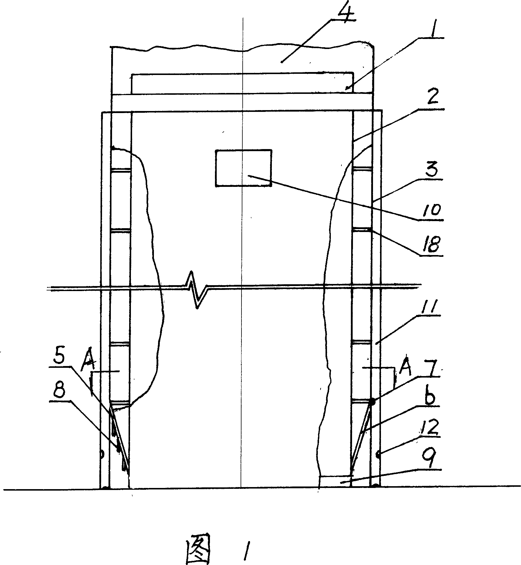
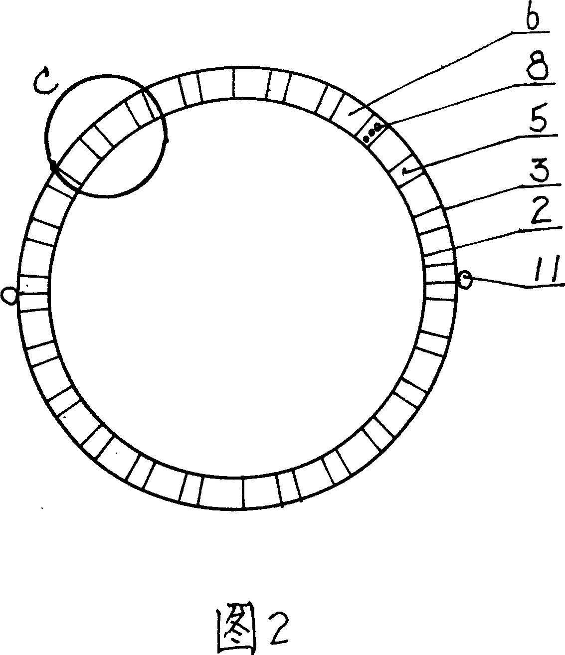
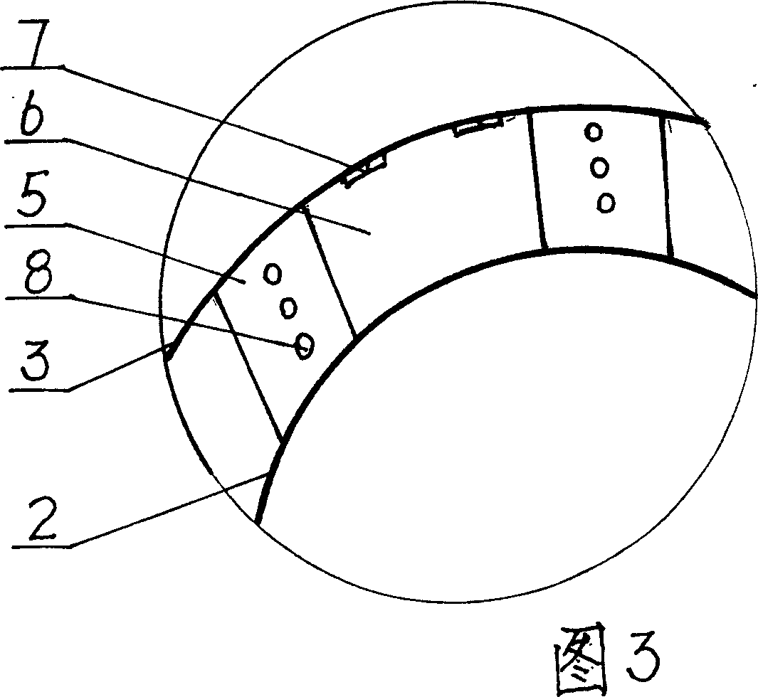
[0038] Concrete barrel (pipe) piles for house construction plus reinforcement cages, as shown in Figures 1-3: the concrete bottom cover, the barrel (pipe) pile with pile caps and pile wings are connected to the vibrating joint 1, and the vibrating joint 1 is connected with the high-frequency hydraulic vibrating hammer 4 through a hydraulic clamp, and then it is integrated with the cavity structure of the inner casing 2 and the outer casing 3 in the middle. Support bar 18, when inner casing 2 and outer casing 3 move downward, can not change its relative position, to ensure the size of the cavity structure, the spud can structure is connected under the hole forming device, and it is formed by the circumference of the cavity structure cross section It consists of a plurality of divided petals that are evenly divided. The divided petals connect the inner sleeve 2 and the outer sleeve 3. At the bottom, the inner sleeve 2 is long and the outer sleeve 3 is short. Therefore, the inner ...

Embodiment 2

[0042] Concrete barrel (pipe) piles for road construction do not add reinforcement cages, as shown in Figures 1-3: the concrete back cover, the barrel (pipe) pile hole former with pile caps and pile wings are exactly the same as in Embodiment 1. The construction process is shown in Fig. 5, Fig. 6 and Fig. 8: place the special concrete-backed winged cylinder (pipe) pile hole former at the foundation to be driven, and use a special laser inclinometer to measure the vertical direction of the hole former. degree; start the high-frequency hydraulic vibratory hammer (or electric vibratory hammer), and drive the tube (tube) pile hole forming device connected to it to vibrate downward; when the bottom of the tube (tube) pile hole forming device sinks into the predetermined design depth , through the high-pressure concrete pump and the nozzle under the high-pressure grouting pipe, concrete mortar is sprayed into the cavity of the bearing layer of the cylindrical pile and the annular cav...


PUM


Abstract

The invention relates to a forming bore equipment with concrete sealing, pipe pile with cap and wing, and construction technology. The equipment is connected with Vibration joint 1 in upper position. The middle part is cavity structure, comprised by inner and outer sleeving 2, 3, with stayed bar. Nether shoe structure is comprised of many sections, which connect inner and outer sleeving 2, 3. Fixed section 5 with convex pillar is welded with inner and outer 2, 3. One end of active section 6 is connected with outer sleeving 3 and iron hinges 7. Two hyperbaric injecting pipes 11, through which concrete is injected into bottom of pipe pile and cavity and sprayed to soil surrounding pipe pile so as to form wing 17, are set outside it. Cavity structure is extracted and reinforcing cage is pressed-in. Cap 13 is added to the tip of pile and sandrock layer 14 and earth grid 15 are lay. It is provided with improving single pile load, reducing pile quantity and so on, and has widely applications.

Description

technical field [0001] The invention belongs to foundation engineering, in particular to a concrete back cover, a cylinder (pipe) pile hole former with pile caps and pile wings and a construction process. Background technique [0002] As we all know, the existing concrete cylinder (pipe) pile hole formers and construction techniques include: ①. Large-diameter cast-in-place pipe pile composite foundation construction method, using an electric vibratory hammer to vibrate downward to drive the pipe pile machine into the foundation, When the cavity structure of the inner and outer casing sinks into the predetermined design depth, concrete is evenly injected into the cavity of the cavity structure of the inner and outer casing through the concrete flow divider to form a pipe pile. The bottom of the pipe pile is not closed, and the wall thickness of the pipe pile is uneven, so that the bearing capacity of this pipe pile is small; In the process of pouring concrete, the boot pile ...

Claims


Application Information

Patent Timeline
Patent Type & Authority Applications(China)
IPC IPC(8): E02D5/38E02D5/62E02D5/72E02D5/48E02D11/00E02D7/18
Inventor 徐东强刘春原
Owner 华北建设集团有限公司
Why Eureka
Try Eureka