Underwater target laser line scanning imaging device

A technology for scanning imaging and underwater targets, applied to lasers, laser components, semiconductor lasers, etc., can solve the problems of difficult imaging processing, high price, volume, weight, and high energy consumption

Inactive Publication Date: 2007-03-21
OCEAN UNIV OF CHINA
View PDF0 Cites 14 Cited by
  • Summary
  • Abstract
  • Description
  • Claims
  • Application Information

AI Technical Summary

Problems solved by technology

The original devices used in range gating and flying line scanning devices are relatively complex and expensive, and the volume, weight, and energy consumption of these two devices are large, and they can only be used on large underwater vehicles. Therefore, the current underwater laser imaging The technology still cannot achieve the purpose of miniaturization, integration and practicality
[0003] However, the flying line scanning technology developed in recent years mostly adopts the synchronous scanning method. It is difficult to maintain strict synchronization between the emitting laser and the optical polyhedron receiving the light, and the scanning mirror is complicated, the cost is high, and the imaging process is difficult.
These reasons have greatly affected the promotion and use of laser flying line scanning

Method used


Image

  • Underwater target laser line scanning imaging device
  • Underwater target laser line scanning imaging device

Examples


Embodiment Construction

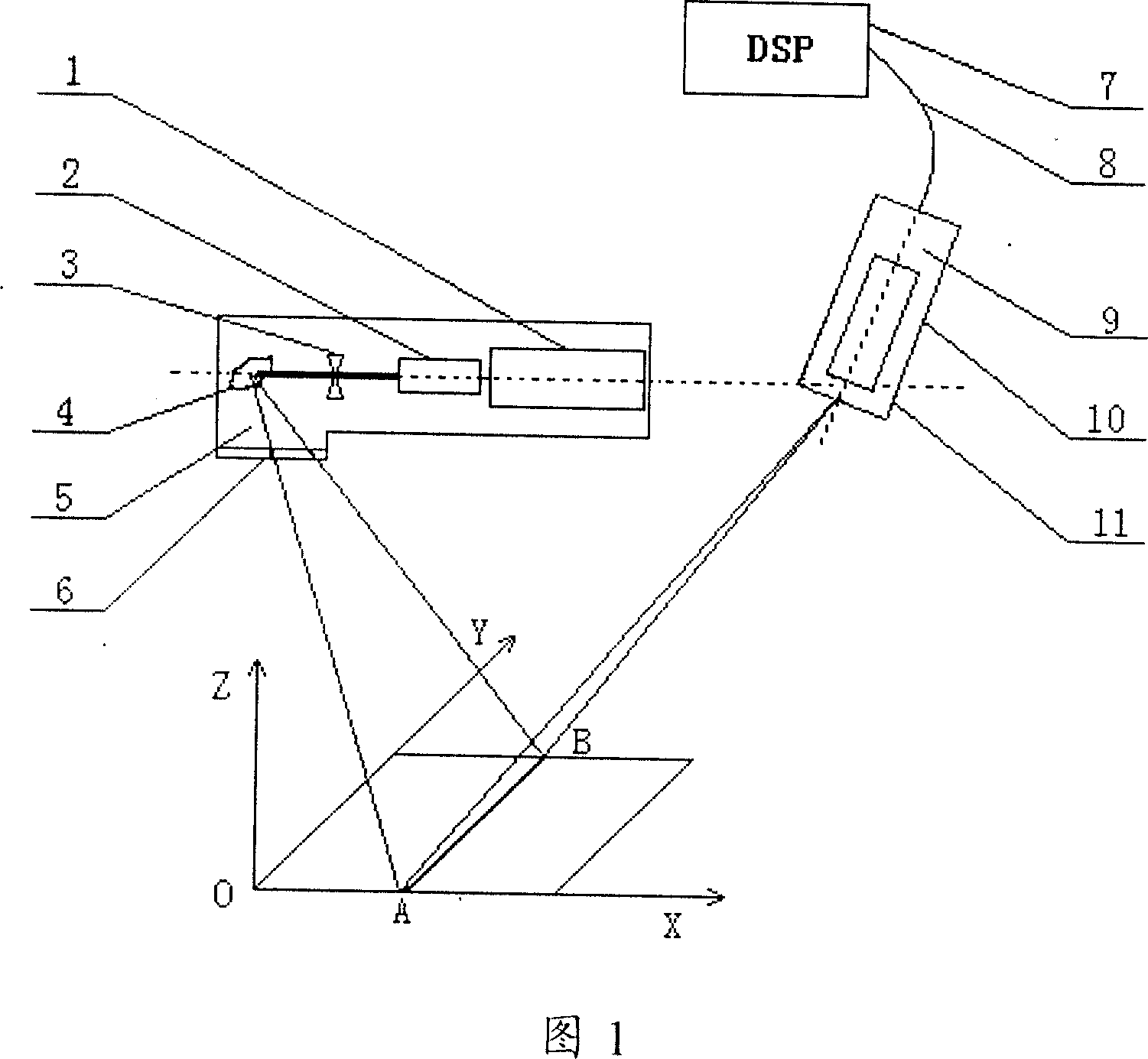
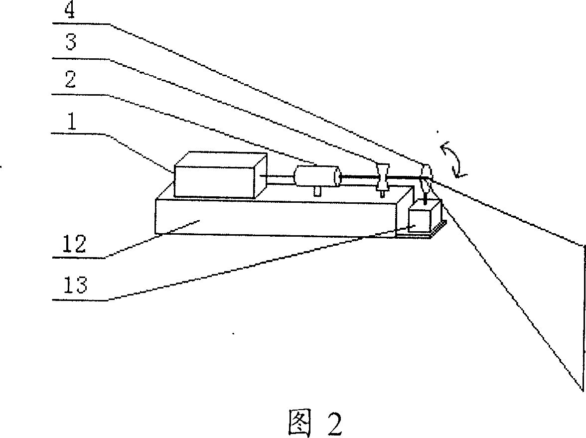
[0012] As Fig. 1, 2, the present invention comprises by the laser device 1 in the watertight housing 6 of underwater band transparent window and beam expander mirror 2 in front thereof, plano-concave cylindrical mirror 3 and the laser emission device 5 that total reflection mirror constitutes, and The receiving device 9 in the watertight casing 11 with a transparent window, and the image processing device 7 on the water connected by the cable 8 are used for synchronous processing to display the detection target in real time. It is characterized in that the transmitting device 5 and the receiving device 9 on the same reference plane are separate body, and the emitting optical axis of the emitting device 5, the receiving optical axis of the adjustable receiving device 9 and the center of the target are on the same plane.

[0013] Emitter 5 comprises laser 1 installed on base 12, beam expander 2, plano-concave cylindrical mirror 3 and total reflection mirror 4 fixed on motor 13 ro...


PUM


Abstract

A scan imaging device for the water object includes the laser in the shell with the transparent window under the water, the laser shot device composed by the extender lens, the plano-concave cylinder lens and the holophote, the receiver in the shell with transparent window and the image processing unit in the water. The electropult and the receiver are separately in the same base plane. The emitting optical axis, the receiving optical axis of the adjusted receiver and the object center are in the same plane. It is loaded on the robot or the ship in the water by the diver and generates the standard image signal to get the clean image. So it can be used for the military and the scientific research.

Description

technical field [0001] The invention belongs to an underwater laser imaging device, in particular to an underwater target laser line scanning imaging device. Background technique [0002] In the existing underwater laser imaging technology, the backscattering problem in the underwater laser propagation process is mainly solved, and the range gating method and the flying line scanning method are usually used. Although these two technologies have achieved gratifying results in underwater detection, there are still many shortcomings. The original devices used in range gating and flying line scanning devices are relatively complex and expensive, and the volume, weight, and energy consumption of these two devices are large, and they can only be used on large underwater vehicles. Therefore, the current underwater laser imaging The technology still cannot achieve the purpose of miniaturization, integration and practicality. [0003] However, the flying line scanning technology de...

Claims


Application Information

Patent Timeline
Patent Type & Authority Applications(China)
IPC IPC(8): G02B26/10H01S5/00H04N5/225G03B17/48
Inventor 刘智深曹锐王义峰张小波王章军
Owner OCEAN UNIV OF CHINA
Why Eureka
Try Eureka