
Digital image sensor locator based on CMOS and locating method

A digital image and positioning device technology, which is applied in the fields of electrical digital data processing, instruments, and graphic reading, can solve the problems of high production process requirements, limited positioning accuracy and positioning range, and expensive use costs, and achieves simple structure and principle, Reduced speed requirements, lightening the effect of heavy tasks

Inactive Publication Date: 2007-03-21
GUANGDONG VTRON TECH CO LTD
View PDF2 Cites 24 Cited by
  • Summary
  • Abstract
  • Description
  • Claims
  • Application Information

AI Technical Summary

Problems solved by technology

Infrared touch screen is a device with relatively high performance and wide application in touch screen positioning technology, but infrared touch screen device has its inherent shortcomings and limitations, such as its application occasions, lighting conditions, and some factors such as the life of infrared components.
The camera positioning technology based on charge-coupled device (CCD) overcomes the shortcomings of infrared positioning technology, but the existing camera positioning touch screen devices, some of which also include digital signal processors (DSP), are expensive to use, complex image processing algorithms, and difficult to produce. High process requirements
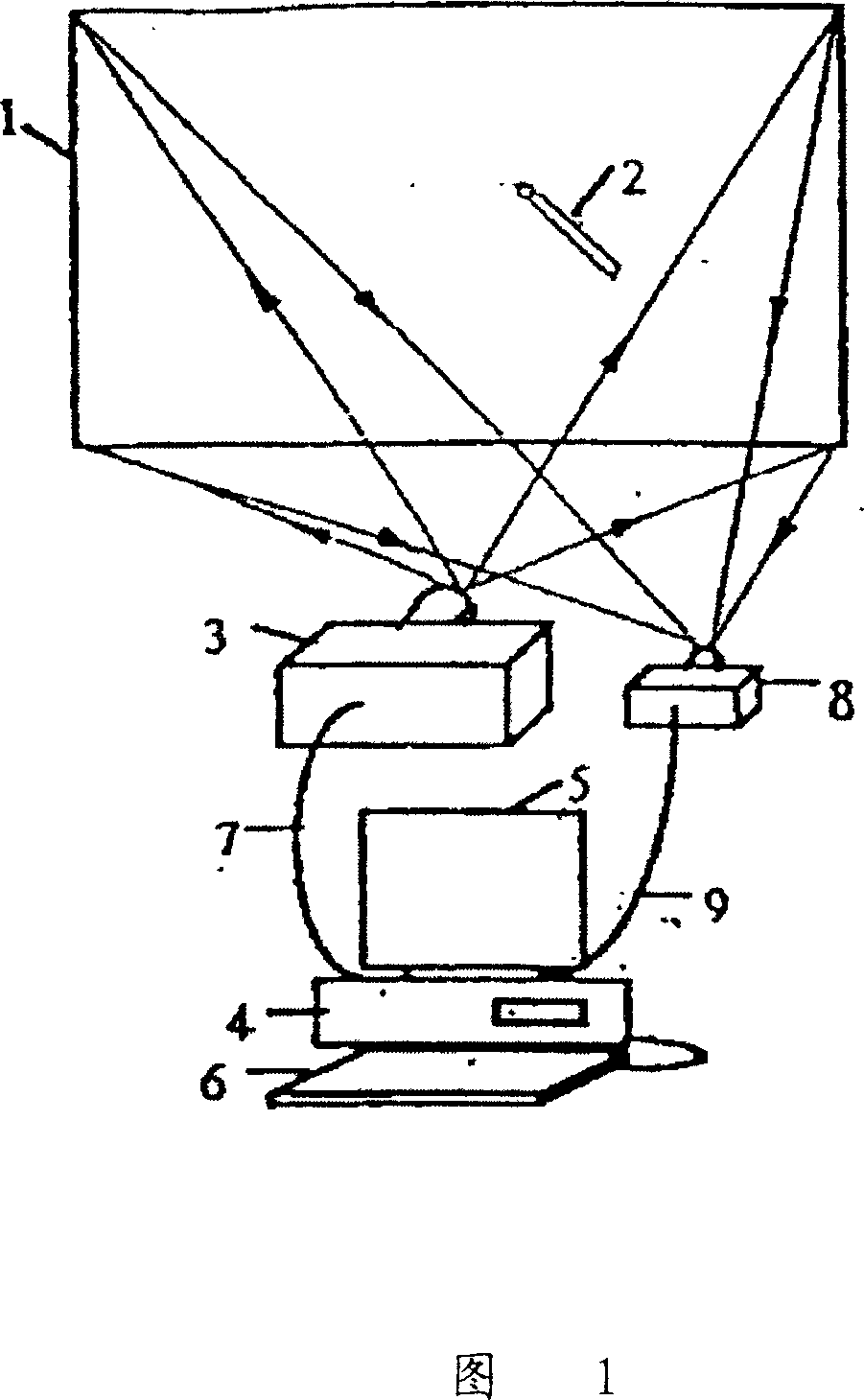
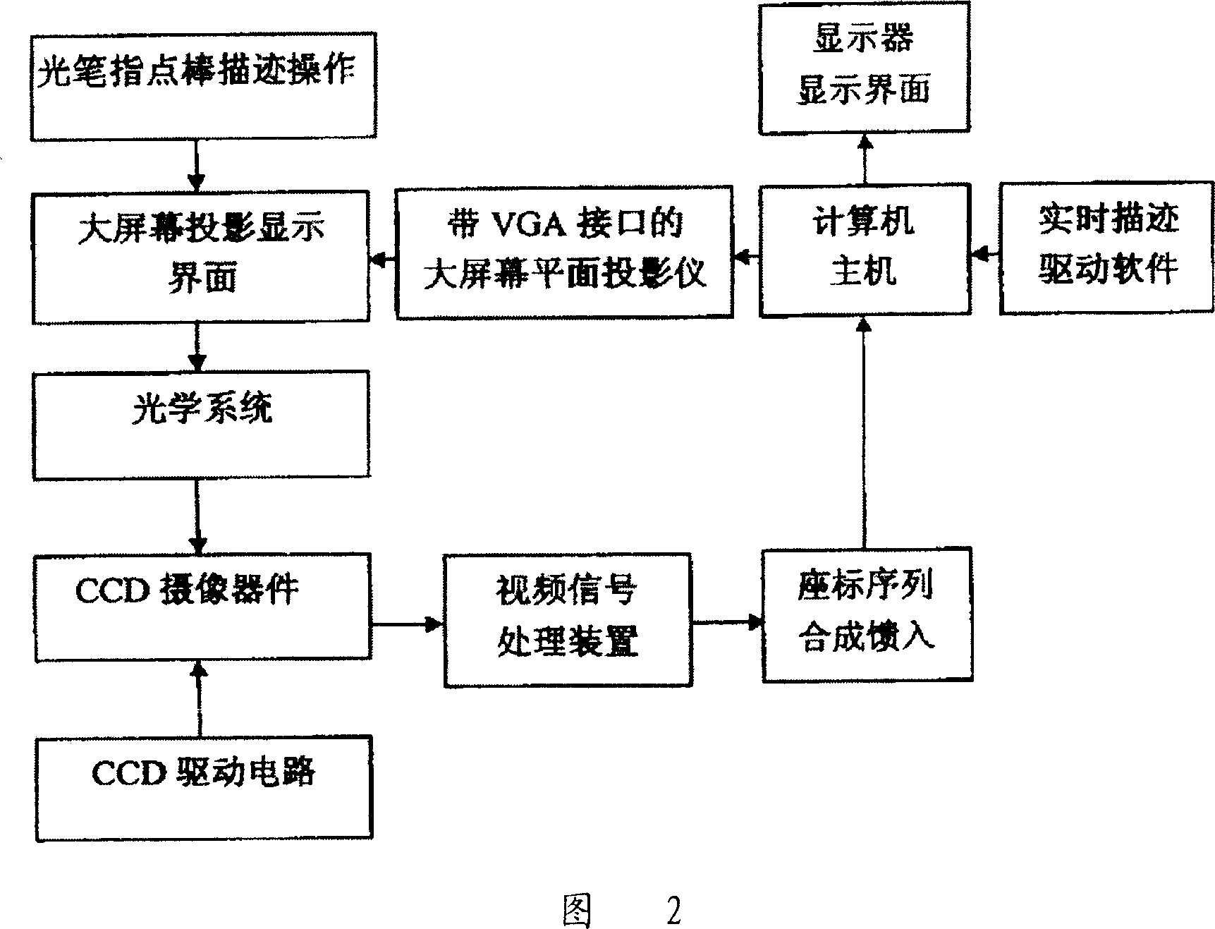
[0003] Existing such as Chinese patent 99110572.9 utilizes a CCD imaging device to detect the imaging of infrared point-like light sources, the output signal of the CCD imaging device is sent to the video signal processing device for processing, and is screened by the longitudinal coordinate circuit and the feature point circuit through preprocessing and The horizontal coordinate circuit counts them, and then the coordinate sequence value of the feature point is synthesized by the coordinate synthesis circuit. The structure and principle of the screen positioning device are shown in Figure 1 and Figure 2. It uses a CCD camera to output analog video signals, and then uses Discrete components such as voltage comparators, potentiometers, resistors and capacitors process them to filter out light point characteristic signals, horizontal frequency signals and field frequency signals. If the CCD imaging device in the patent uses an existing analog video camera, its accuracy is relatively Low, and if a high-resolution camera is used, its cost is too high to meet people's requirements for low cost and applicable
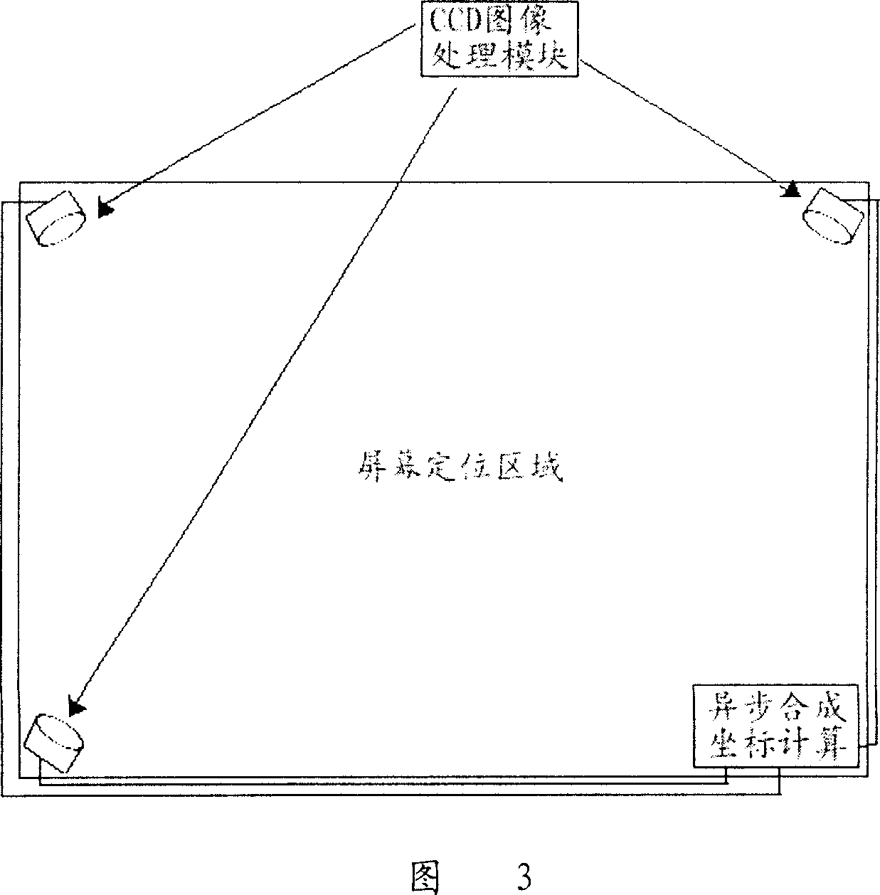
U.S. Patent 20040108996 uses two or more CCDs to continuously acquire target images, and then uses a digital signal processor (DSP) to perform image synthesis processing on the images obtained by each camera, and extracts images containing writing pens from complex background images. The location information of the device, its device structure and principle are shown in Figure 3 and Figure 4, the image processing algorithm is more complex, the cost is more expensive; at the same time, under the same technical conditions, its positioning accuracy and positioning range will be directly affected by the existing camera limited by pixels of
[0004] The digital signal processor (DSP) chip has many pins, the chip welding process requires high requirements, the production process is complicated, the debugging is difficult, and the debugging success rate is very low.
DSP inherently has powerful image processing and computing functions, but generally requires additional Flash, data storage and E 2 PROM, etc., which will greatly increase the cost of the product and the complexity of production and debugging

Method used


Image

  • Digital image sensor locator based on CMOS and locating method
  • Digital image sensor locator based on CMOS and locating method
  • Digital image sensor locator based on CMOS and locating method

Examples


Embodiment Construction

[0026] Please refer to Fig. 5, which is a schematic diagram of an embodiment of a screen positioning device based on a CMOS digital image sensor in the present invention. It is a writing screen; an infrared luminescent writing pen; a writing screen formed by imaging infrared light waves emitted by an infrared luminescent writing pen; The processing calculation module includes an image data preprocessing circuit (such as FPGA or CPLD or a circuit composed of some discrete chips, etc.), a single-chip microcomputer; a PC connected with the processing calculation module to perform man-machine interactive operation actions. The working principle of the screen positioning device based on the CMOS digital image sensor is shown in FIG. 6 . The image data preprocessing circuit usually includes the following circuits: image data acquisition, image data comparison, useful image data compression, memory, compressed data output, etc.

[0027] The positioning method of the screen positioni...


PUM


Abstract

This invention discloses a screen locating device based on CMOS digital imaging sensor which consists of no less than one optical pen, a screen, a optical lens, a CMOS digital imaging sensor connected to the optical lens, a processor module connected to the sensor and a PC connected to the module. This equipment shows many advantages such as structure briefness, principle simpliness, less image data to be processed and low cost.

Description

【Technical field】 [0001] The invention relates to a positioning device and a positioning method based on a CMOS digital image sensor, in particular to a screen positioning device and a positioning method for simple and precise positioning in a digital grayscale image. 【Background technique】 [0002] The touch screen is an important input device for human-computer interaction between people and multimedia computers. The touch screen positioning technology based on the commonly used intelligent interactive electronic whiteboard is widely used. At present, touch screen positioning technologies and methods include resistive, capacitive, infrared, surface acoustic wave, ultrasonic and camera positioning principles in terms of working principles. Infrared touch screen is a device with relatively high performance and wide application in touch screen positioning technology, but infrared touch screen device has its inherent shortcomings and limitations, such as its application occas...

Claims


Application Information

Patent Timeline
IPC IPC(8): G06F3/01G06F3/042G06F3/033G06K11/06G06F3/0354G06F3/041
Inventor 卢如西张军杨月
Owner GUANGDONG VTRON TECH CO LTD
Learn More