Engine common in joggle type
A technology of constant meshing and starter, which is applied in the direction of engine components, engine starting, machine/engine, etc. It can solve the problems of cost increase and other problems, and achieve the effect that the production cost will not increase, the size and cost will not increase
- Summary
- Abstract
- Description
- Claims
- Application Information
AI Technical Summary
Problems solved by technology
Method used
Image
Examples
no. 1 example
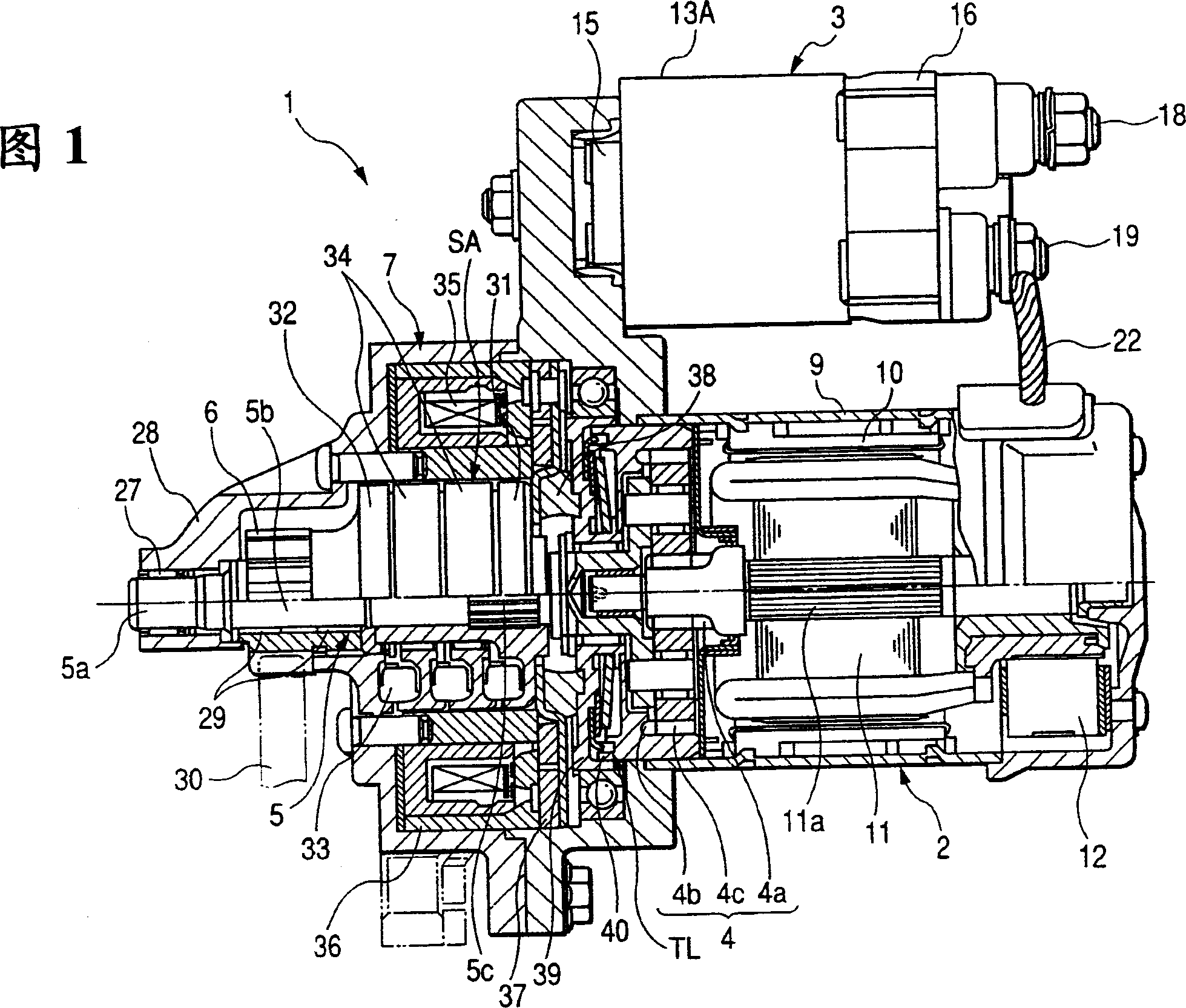
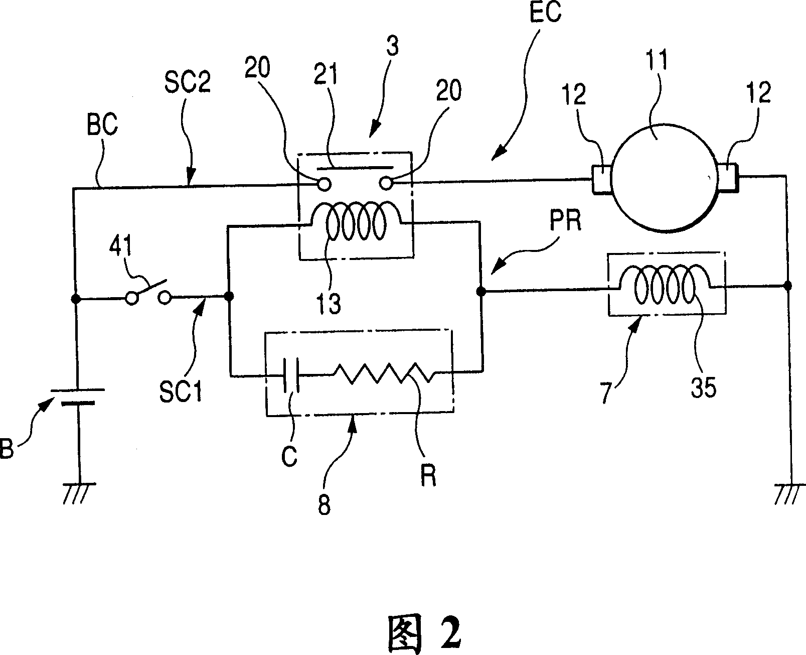
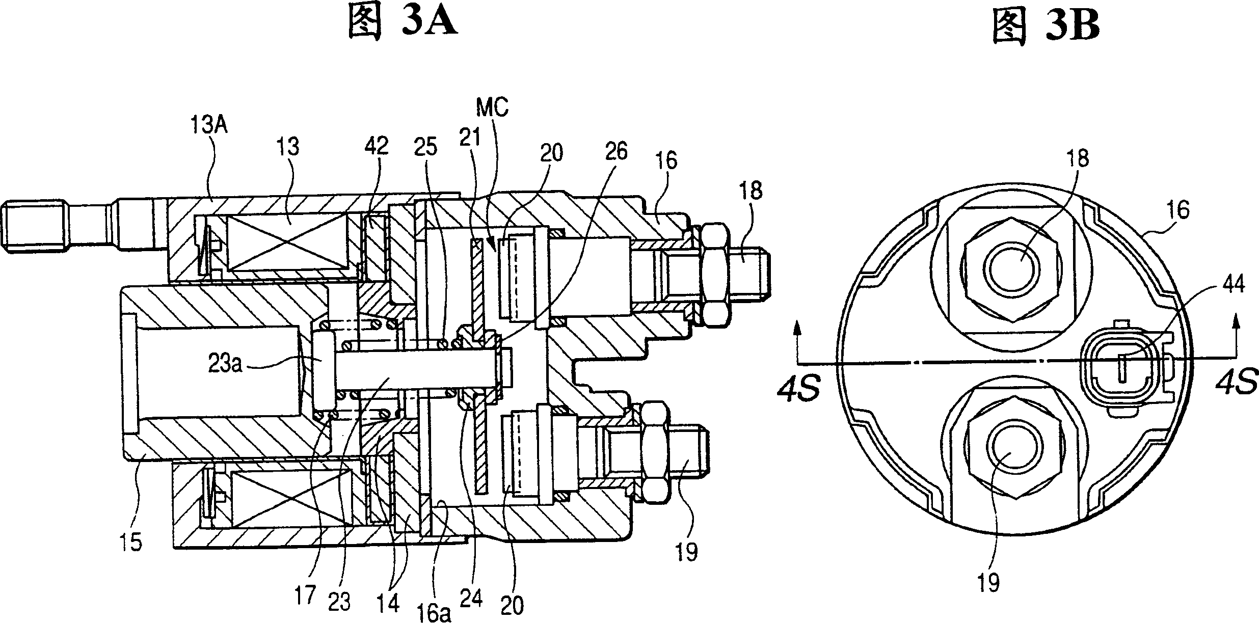
[0056] Referring to Figures 1 and 2, there is shown a starter 1 according to an embodiment of the present invention. The starter 1 includes: a motor 2 for generating output torque, and an electromagnetic switch 3 arranged in an excitation circuit (also called a motor circuit) EC of the motor 2 for closing or opening a main contact MC (described below ); connected with the motor 2 to reduce the speed reduction gear set 4; the output shaft 5, the output torque of the motor 2 is transmitted to the output shaft through the reduction gear set 4; Gear 6; the electromagnetic clutch 7 that can establish or interrupt the torque transmission between the motor 2 and the output shaft 5; and the delay circuit 8 (see Fig. 2 ) that is arranged in the excitation circuit EC, can make the electromagnetic switch 3 after the electromagnetic clutch is energized power on for a predetermined delay time. The starter 1 can be applied to the automatic stop and restart system of the engine (also called...
no. 2 example
[0092] In the starter 1 of the second embodiment, the structure of the electromagnetic clutch 7 is designed such that the clutch plate 37 can move a given axial stroke (equal to the distance between the end surface of the clutch housing 36 and the clutch plate) in the axial direction when attracted by the electromagnet. The clutch disc 37 between 37 is used as the axial gap for axial displacement), or the clutch coil 35 is designed such that its attractive force makes the clutch disc 37 attracted by the electromagnet to enter the engaged state before the armature 11 starts to rotate.
[0093] That is to say, the electromagnetic switch 3 that can close or open the main contact MC is designed so that the main contact MC is not closed when the electromagnetic coil 13 is energized, but when the movable core 15 moves a given axis due to the attractive force of the electromagnet. It closes only after the stroke. Therefore, there is a time delay between the energization of the electr...
PUM
 Abstract
Description
Claims
Application Information
 - R&D
- Intellectual Property
- Life Sciences
- Materials
- Tech Scout
- Unparalleled Data Quality
- Higher Quality Content
- 60% Fewer Hallucinations
Browse by: Latest US Patents, China's latest patents, Technical Efficacy Thesaurus, Application Domain, Technology Topic, Popular Technical Reports.
© 2025 PatSnap. All rights reserved.Legal|Privacy policy|Modern Slavery Act Transparency Statement|Sitemap|About US| Contact US: help@patsnap.com


