Fractional gasifying furnace for coal and coke gasification

A staged gasification furnace technology, applied in the manufacture of combustible gas, petroleum industry, combined combustion mitigation, etc., can solve the problems that the reaction conditions in the furnace cannot be optimized, and the oxygen distribution cannot be adjusted, so as to improve volume utilization and smooth flow , the effect of reducing space

Active Publication Date: 2007-04-11
TSINGHUA UNIV +1
View PDF0 Cites 14 Cited by
  • Summary
  • Abstract
  • Description
  • Claims
  • Application Information

AI Technical Summary

Problems solved by technology

[0003] Solve the problem: the present invention solves the problem that the reaction conditions in the furnace cannot be optimized due to the fact that the distribution of oxygen in the gasifier cannot be adjusted, and provides a staged gasifier, which adopts the method of adding oxygen in stages to adjust the distribution of oxygen in the furnace. Establish different temperature zones in the furnace and optimize the reaction conditions. The oxygen added in the second stage is at the lower edge of the reflow zone, which can disturb the gas in the "reflow zone" in the furnace, and strengthen the mass transfer and heat transfer of the raw fuel and oxygen in this zone, so that This low-efficiency recirculation zone becomes a high-efficiency reaction zone, improving the volume utilization of the gasifier

Method used


Image

  • Fractional gasifying furnace for coal and coke gasification
  • Fractional gasifying furnace for coal and coke gasification
  • Fractional gasifying furnace for coal and coke gasification

Examples


Embodiment 1

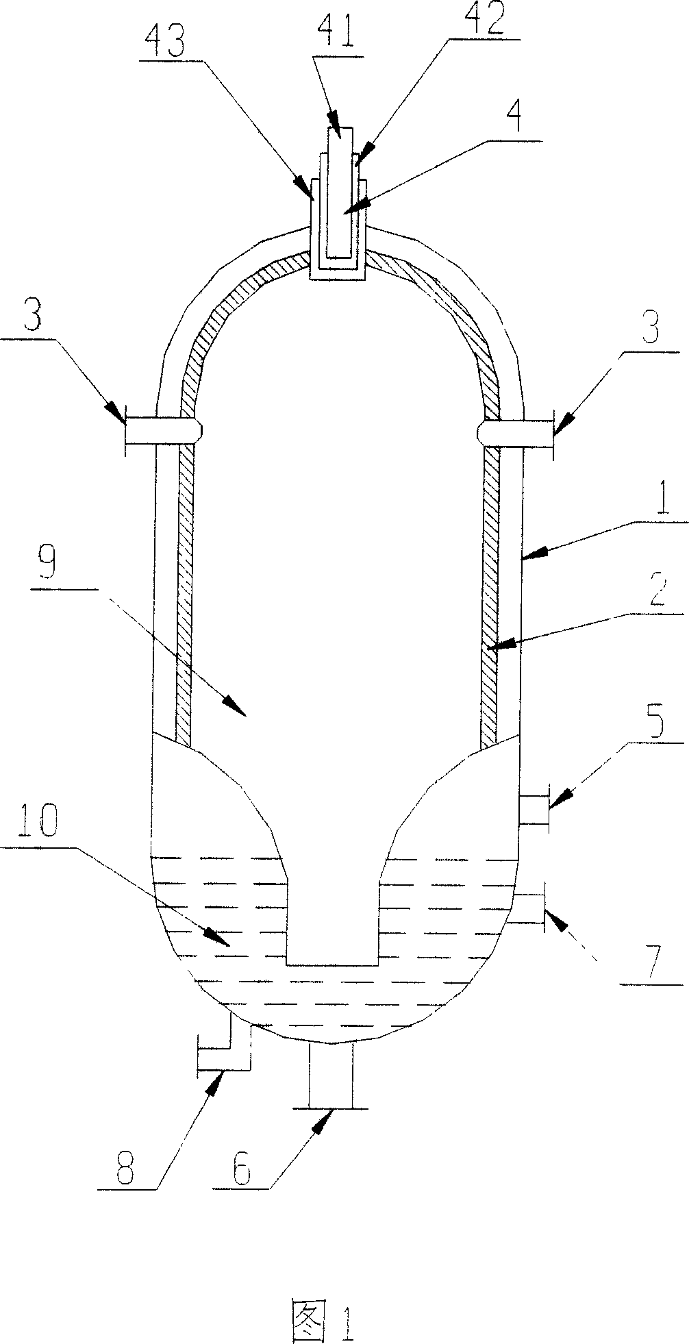
[0013] Embodiment 1: see Fig. 1. The staged gasifier for coal and coke gasification in this embodiment is composed of a steel pressure-resistant shell 1 and a refractory layer 2 therein, forming a furnace body 9 . The crude gas outlet 5 is installed at the lower part of the side wall of the pressure-resistant shell 1 , and the slag outlet 6 is installed at the bottom of the pressure-resistant steel shell 1 . A water quenching system 10 is provided at the lower part of the body of furnace 9, and the water quenching system 10 is equipped with a drain port 8 and a water replenishment port 7 at the lower part of the pressure-resistant casing 1. The present invention is characterized in that the secondary oxygen nozzle 3 is arranged at the On the side wall top of the pressure housing 1, there are preferably two secondary oxygen nozzles 3, as shown in the figure, symmetrically arranged on the pressure-resistant housing 1, and the position that the secondary oxygen nozzles 3 is set s...

Embodiment 2

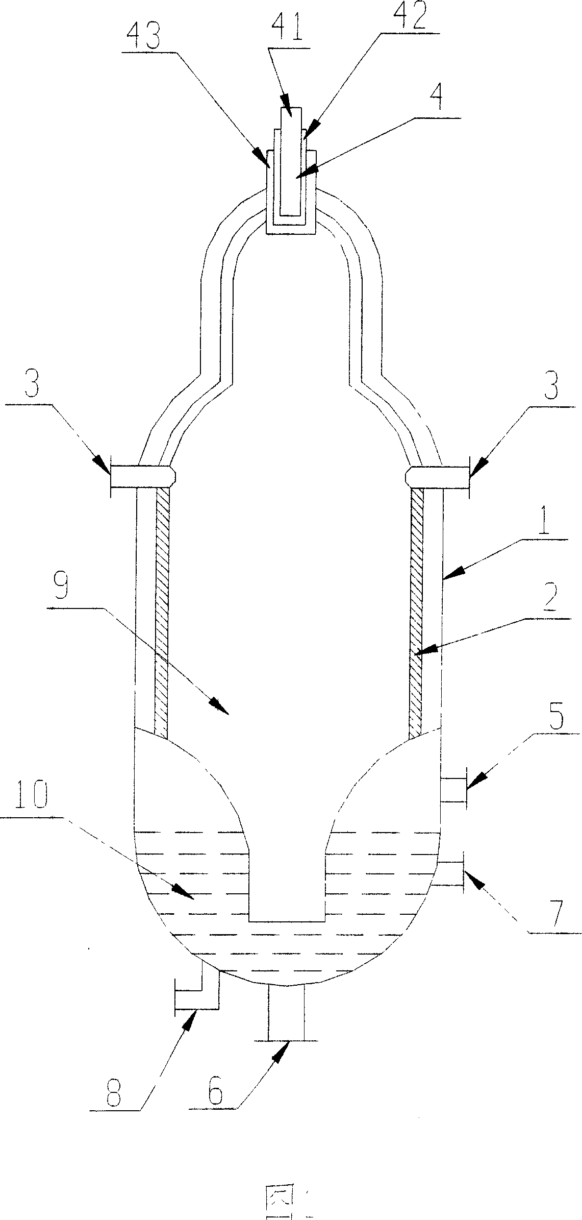
[0017] Embodiment 2: see Fig. 2. In the staged gasifier for coal and coke gasification in this embodiment, the upper low-temperature non-slag zone and the lower high-temperature slag zone are directly connected with unequal diameters, and the diameter of the upper low-temperature non-slag zone is smaller than the lower high-temperature slag zone. For example, according to the position of the recirculation zone, the recirculation zone and the following parts are set to a larger diameter, which is convenient for better temperature control according to the fuel properties. The other structures of this embodiment are the same as those of Embodiment 1.

Embodiment 3

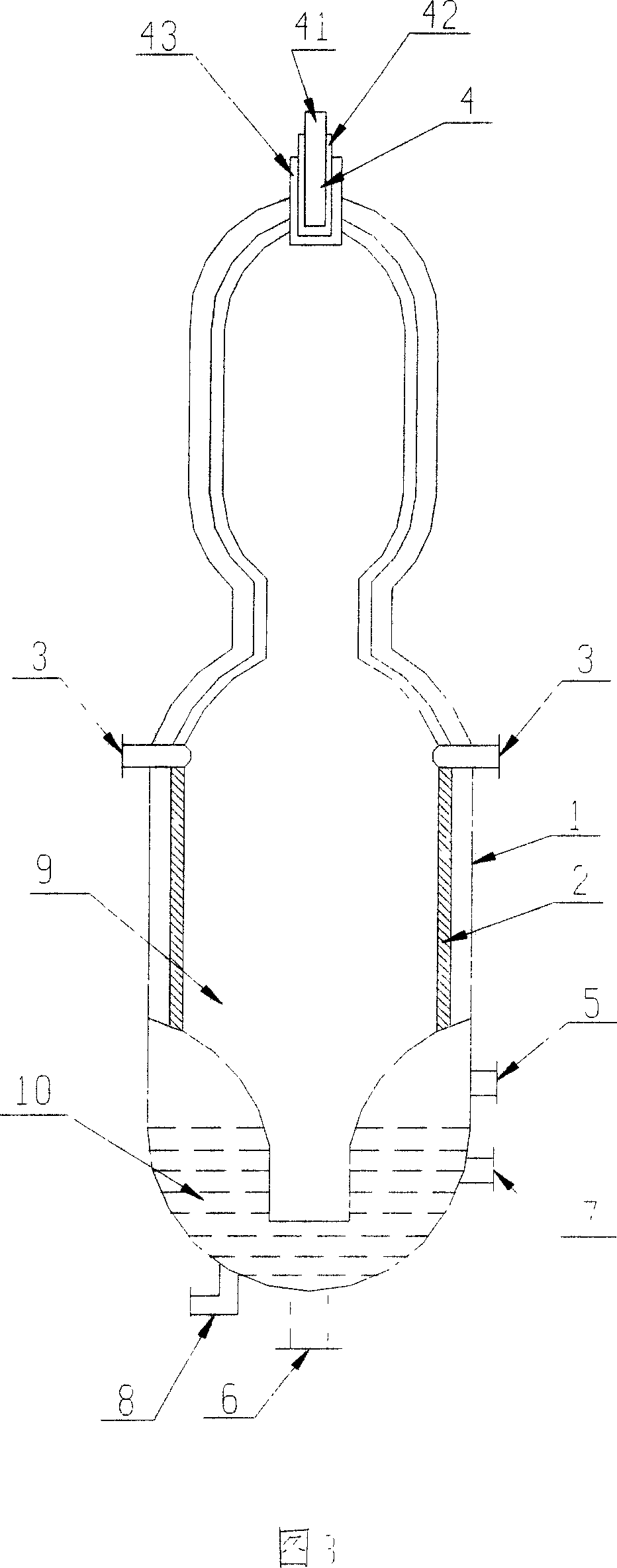
[0018] Embodiment 3: see Fig. 3. In the staged gasifier for coal and coke gasification in this embodiment, the upper low-temperature non-slag zone is connected with the lower high-temperature slag zone in reduced diameter. The upper low-temperature non-slag zone of this structure has a longer space area, which is suitable for higher calorific value. Low raw fuel can provide a larger and more sufficient primary gasification space, making it close to the slag temperature of 1000 °C. Other constructions of this example are the same as Example 1.


PUM


Abstract

The present invention is one stepped gasifying furnace for gasifying coal and coke to produce coarse gas containing CO and H2. The stepped gasifying furnace includes pressure resisting casing, refractory layer, coarse gas outlet, cinder outlet, water chilling system in the lower part of the furnace body, and feeding burner in the top to supply oxygen and fuel. It features the secondary oxygen nozzle set in the reflux region of the furnace body to regulate oxygen distribution inside the furnace and establish different temperature regions, so as to optimize the reaction condition, prolong the service life of the feeding burner and raise the volume utilizing rate of the furnace.

Description

technical field [0001] The invention relates to a staged gasification furnace capable of gasifying coal and coke to produce crude gas containing carbon monoxide and hydrogen. Background technique [0002] Existing gasifiers that can gasify coal and coke to generate crude gas containing carbon monoxide and hydrogen generally use the method of one-time input of raw fuel and oxygen. Since the reaction state in the gasification furnace cannot be artificially controlled, the temperature distribution and air flow state in the furnace are unreasonable. Although the disclosed structure of the No. 021210861 invention patent application non-slag-slag gasifier applied by one of the inventors of the present application involves two oxygen supplies, but, because two furnace bodies must be taken, the structure is complicated and the cost is significantly increased. Improvement, not only the pipeline connection brings loss, but also the control is difficult, and the gasification furnace w...

Claims


Application Information

Patent Timeline
Patent Type & Authority Applications(China)
IPC IPC(8): C10J3/20
CPCY02E20/18
Inventor 顾大地岳光溪
Owner TSINGHUA UNIV
Why Eureka
Try Eureka