Energy feedback power unit

A technology of power unit and energy feedback, which is applied in the direction of output power conversion device, conversion of AC power input to AC power output, conversion of AC power input to DC power output, etc. Complicated structure and other problems, to achieve good promotion and application prospects, reduce harmonic pollution, and simple device structure

Active Publication Date: 2007-04-18
北京合康新能变频技术有限公司
View PDF0 Cites 22 Cited by
  • Summary
  • Abstract
  • Description
  • Claims
  • Application Information

AI Technical Summary

Problems solved by technology

This not only wastes electric energy in vain, but also complicates the structure.
[0005] For applications that require lowering heavy objects or emergency shutdown, the power unit series multilevel high-voltage inverter requires that the power unit should have energy feedback function. However, the application of this energy feedback working method in the high-voltage field is very complicated. How to It is a technical difficulty that has plagued technicians in the industry for many years to feed back electric energy into the power grid without or little impact on the power supply quality of the power grid; especially for power unit series multi-level high-voltage inverters, it uses low-voltage power The high-voltage output is realized by connecting the units in series, and at the same time, the phase-shifting function of the transformer is used to realize a perfect harmonic-free high-voltage inverter on the input side. It is more difficult for this kind of high-voltage inverter to realize the energy feedback function, and there has been no good technology so far. solution

Method used


Image

  • Energy feedback power unit
  • Energy feedback power unit
  • Energy feedback power unit

Examples


Embodiment Construction

[0023] In order to make the object, technical solution and advantages of the present invention clearer, the present invention will be further described in detail below in conjunction with the accompanying drawings.

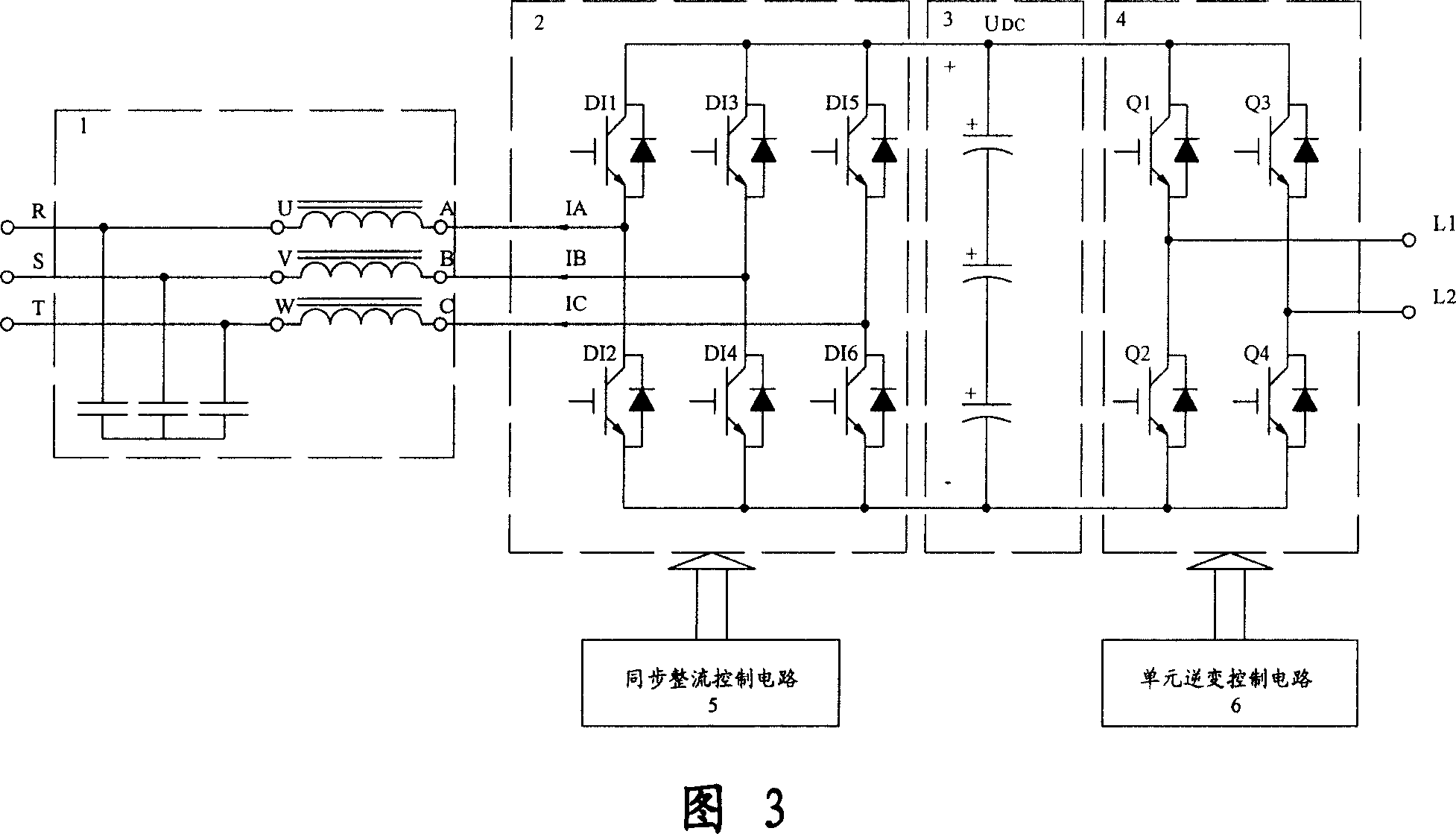
[0024] Referring to Fig. 3, the control circuit composition structure of the energy feedback power unit of the present invention is introduced: a filter circuit 1 composed of a three-phase capacitor and a three-phase reactor connected in sequence, a three-phase synchronous rectification bridge composed of an insulated gate bipolar transistor IGBT 2. A DC filter circuit 3 composed of capacitors, a unit inverter bridge 4 composed of IGBTs, and a synchronous rectification control circuit 5 and a unit inverter that respectively control the working states of the three-phase synchronous rectification bridge 2 and the unit inverter bridge 4 variable control circuit 6; wherein two control circuits 5 and 6 are the innovation key of the device of the present invention: the u...


PUM


Abstract

The invention is an energy feedback power unit used in series power unit-type high voltage inverter and implementing four-quadrant operating ability, and its control circuit comprises: filter circuit composed of three-phase capacitors and three-phase reactors, three-phase synchronous rectifier bridge composed of IGBTs, DC filter circuit composed of capacitors, unit inverter bridge composed of IGBTs, and synchronous rectification control circuit and unit inversion control circuit controlling the operating states of the three-phase synchronous rectifier bridge and unit inverter bridge, respectively. And it has rectifying and energy feedback functions, and simple structure, low losses, easy to implement, low-cost, having high power factor but no harmonic pollution to electric network. And the high voltage transformer composed by it has all functional characteristics of common high voltage transformers and ability to convert kinetic energy or potential energy into electric power to feed back to the electric network on the conditions of fast system braking or weight dropping.

Description

technical field [0001] The invention relates to a main component of a high-voltage frequency converter, specifically, an energy feedback power unit for a high-voltage frequency converter of series power unit type and capable of four-quadrant operation; it belongs to the technical field of power electronic equipment. Background technique [0002] The frequency converter is a power conversion device that converts the power frequency power supply into an adjustable frequency by using the on and off functions of semiconductor power devices. The device first converts the electric energy of the AC power supply into DC power, and then converts the DC power into AC power with variable frequency to drive the load. With the rapid development of microelectronics and power electronics technology, as a product of the development of power electronics technology in the 21st century, high-voltage frequency converters have been widely used in many fields of the national economy (such as ther...

Claims


Application Information

Patent Timeline
Patent Type & Authority Applications(China)
IPC IPC(8): H02M5/44H02M7/525G05F1/66
CPCH02M5/4585
Inventor 杜心林
Owner 北京合康新能变频技术有限公司
Why Eureka
Try Eureka