

Follow-up control apparatus of miniature airborne cradle head
A tracking control, minicomputer technology, applied in the direction of comprehensive factory control, electrical program control, control using feedback, etc., can solve the problem of no serial port, no sensor, etc., to achieve the effect of guaranteed tracking, good adaptability, and small size
- Summary
- Abstract
- Description
- Claims
- Application Information
AI Technical Summary
Problems solved by technology
Method used
Image

Examples
Embodiment Construction
[0019] A preferred embodiment of the present invention is described as follows in conjunction with accompanying drawing:
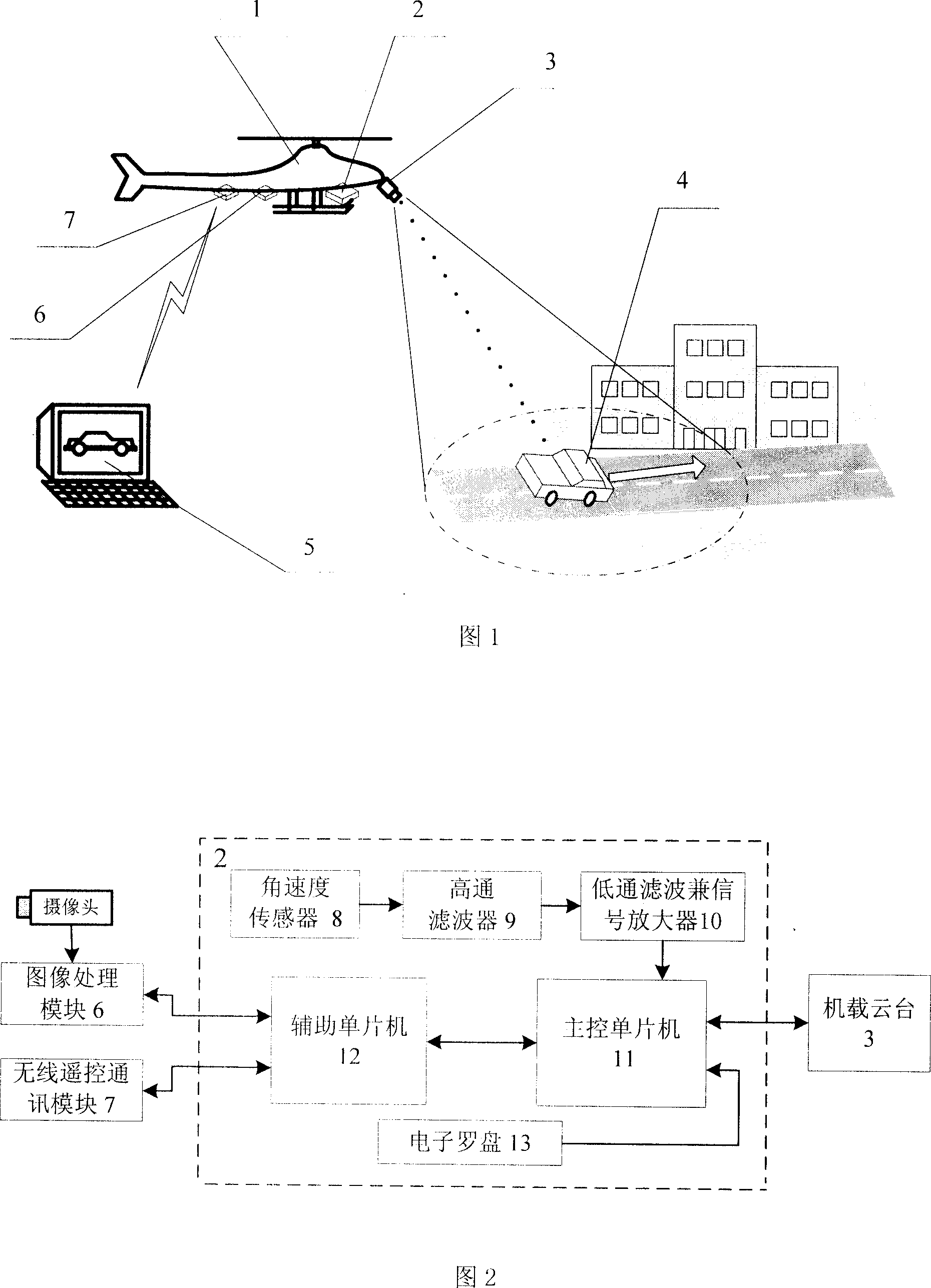
[0020] Referring to FIG. 1 , the small airborne pan-tilt tracking control device 2 is applied to a micro unmanned aerial vehicle 1 carrying a camera to track a ground moving target 4 . The device 2 , the airborne platform 3 , the image processing module 6 and the wireless remote control communication module 7 are all loaded on the miniature unmanned aerial vehicle 1 . The airborne gimbal 3 can move in two degrees of freedom, it is driven by an integrated motor, and has a camera and an RS-232 control interface. Among them, 5 are ground control stations. The function of this device 2 is to collect and process the attitude angle and angular velocity information of the aircraft, then fuse the tracking target image information sent by the image processing module 6, and calculate the moving angles of the airborne gimbal in two directions through a certain track...
PUM
 Abstract
Description
Claims
Application Information