
Process for the production of plasma displays with distributed getter material and displays thus obtained

一种等离子显示板、吸气材料的技术,应用在电气元件、充气放电管、混合气体吸收等方向,能够解决蔓延并且占据等问题

Inactive Publication Date: 2007-05-23
SAES GETTERS SPA
View PDF8 Cites 0 Cited by
  • Summary
  • Abstract
  • Description
  • Claims
  • Application Information

AI Technical Summary

Problems solved by technology

However, also this solution presents a significant constructional difficulty, in fact, in order to deposit the getter selectively only on the top surface of the ribs, a very precise masking operation is necessary to avoid material spreading along the sidewalls. and occupy the area assigned to phosphors (or cover them, if these already exist)

Method used


Image

  • Process for the production of plasma displays with distributed getter material and displays thus obtained
  • Process for the production of plasma displays with distributed getter material and displays thus obtained
  • Process for the production of plasma displays with distributed getter material and displays thus obtained

Examples


Embodiment Construction

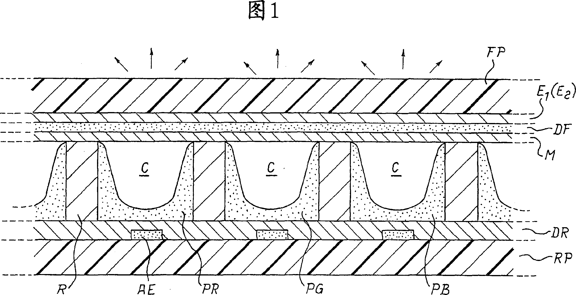
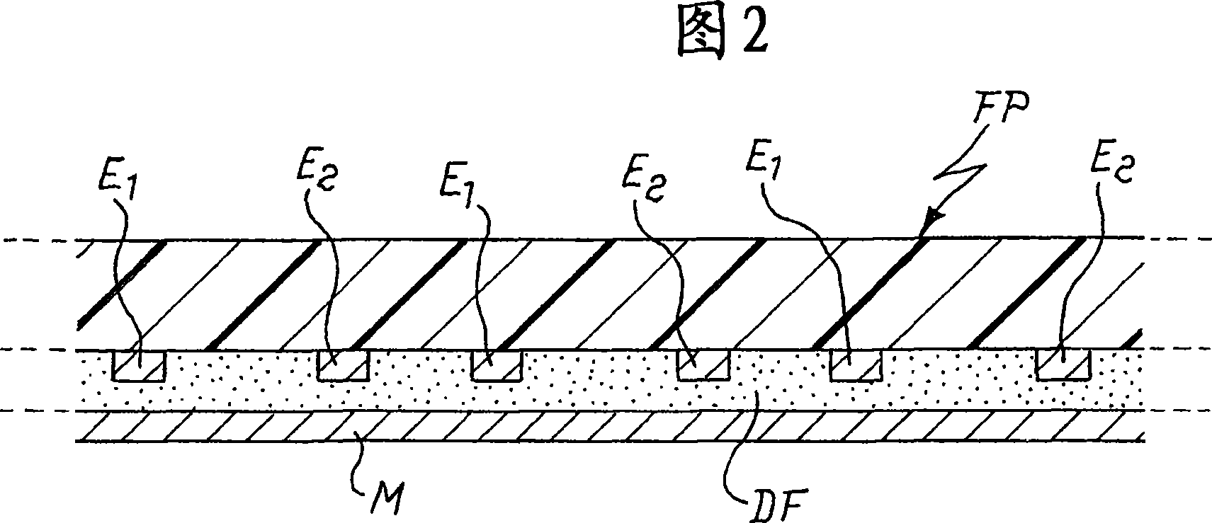
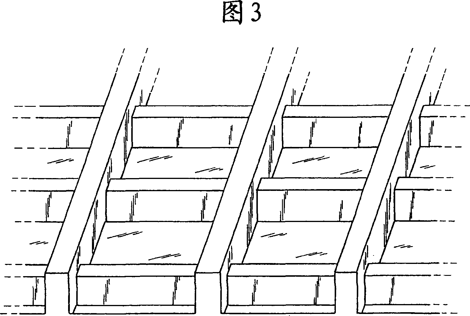
[0030] Figures 1-5 have been described in the Introduction.

[0031] The process of the invention differs from the known processes only in that the manufacture of the front glass plate includes a step of forming a number of getter deposits on the surface, which in the finished display faces the inner space, located in particular corresponding to the contact surface with the upper part of the ribs s position. The getter deposition can be formed on the flat surface of the MgO layer (M in FIG. 1 ) or in grooves formed in this layer. The invention is neutrally applicable in the chamber manufacturing process of suction ducts or PDPs.

[0032] Figure 6 shows various steps characterizing the operation of the invention (in this figure, the front glass plate is shown inverted relative to Figures 1-5). During step a, on the surface of the magnesium oxide layer on which the getter deposition has to be formed, a mask 60 provided with apertures 61, 61', ... is aligned, geometrically corr...


PUM


Abstract

A manufacturing process for the production of plasma display panels (80) is described which allows to obtain in a simple way displays wherein, in contact with the atmosphere present in channels (C) or cells of the display, getter materials deposits (81, 81', ...) are present.

Description

technical field [0001] The invention relates to a process for manufacturing a plasma display panel with distributed getter material; the invention also relates to a display obtained according to the process of the invention. Background technique [0002] A plasma display panel is known by the abbreviation PDP, which will be used below. [0003] The PDP consists of two planar glass parts, a front one and a rear one, sealed at their peripheries by a low-melting glass glue. In this way, a closed space is formed between the two glass parts, filled with a noble gas mixture and containing the functional components, as detailed below; typically, the noble gas mixture includes neon and xenon, the latter being present in an amount of about 4-15% . [0004] The operating principle of the PDP is based on the conversion of ultraviolet rays from so-called phosphors to visible light when a discharge is generated in a rare gas mixture. To form an image, multiple light sources of small s...

Claims


Application Information

Patent Timeline
Patent Type & Authority Applications(China)
IPC IPC(8): H01J9/385H01J17/24
CPCH01J9/40H01J9/385H01J2217/49264H01J9/39H01J11/52
Inventor 乔治·隆戈尼科拉多·卡雷蒂斯特凡诺·托米内蒂
Owner SAES GETTERS SPA
Learn More