Confocal micro imaging system using dummy pinhole

A technology of confocal microscopic imaging and virtual pinholes, which is applied in the field of confocal microscopic systems, can solve the problems of light energy loss, resolution reduction, troublesome cleaning of pinholes, etc., and achieve the effect of convenient adjustment and positioning and simple operation

Inactive Publication Date: 2007-05-30
NANKAI UNIV
View PDF0 Cites 45 Cited by
  • Summary
  • Abstract
  • Description
  • Claims
  • Application Information

AI Technical Summary

Problems solved by technology

[0003] However, traditional confocal microscopy systems use a physical confocal pinhole, such as the core diameter of an optical fiber
In the actual practical process, the following problems usually exist in the physical confocal pinhole: the size of the pinhole is generally in the range of microns, and a precise and stable three-dimensional positioning device is required. After precise and cumbersome adjustments, the pinhole is adjusted to the focus position of the collecting lens, otherwise it will easily cause problems such as loss of light energy and resolution reduction; the size of the pinhole cannot be adjusted and changed at will according to the actual practical situation; after a long time, the pinhole and the focus position are prone to deviation. In addition, there are still problems such as pinhole blockage and pinhole cleaning troubles.

Method used


Image

  • Confocal micro imaging system using dummy pinhole
  • Confocal micro imaging system using dummy pinhole
  • Confocal micro imaging system using dummy pinhole

Examples


Embodiment

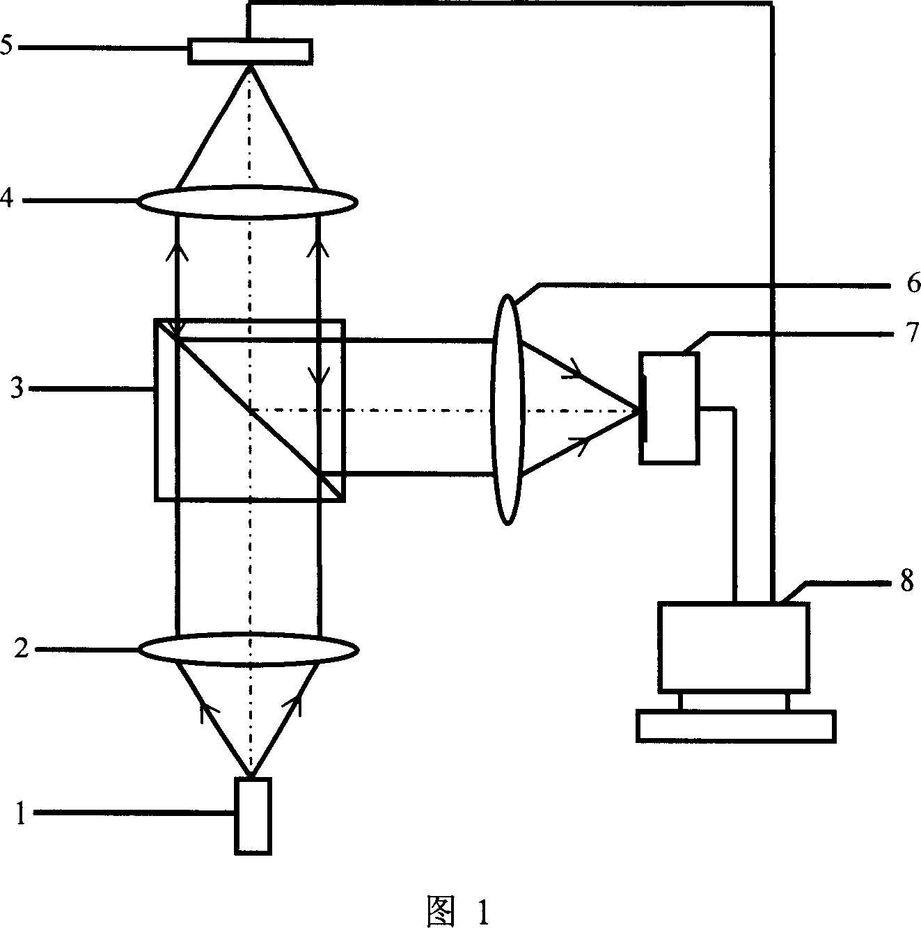
[0043] Figure 1 shows the schematic diagram of the optical path of the confocal microscopic imaging system using a virtual pinhole, point light source 1, collimator lens 2, beam splitter 3 and microscopic objective lens 4, which are sequentially connected in optical path to form the illumination optical path of the system; The system 5 controls the movement of the sample to be measured; the microscope objective lens 4, the beam splitter 3, the collecting lens 6, and the CCD7 are sequentially connected in an optical path to form the detection optical path of the system; the computer 8 controls the scanning system 5 and the CCD7, and performs data acquisition, processing and Image reconstruction. In this embodiment, the plan apochromatic objective lens of Olympus is adopted as the microscope objective lens 4, and the numerical aperture is 0.4; the scanning system 5 adopts the P-611.3S piezoelectric ceramic three-dimensional translation stage of the German PI company, the precisio...


PUM


Abstract

The invention relates to a confocal imaging system in fields of optical microimaging, it is a confocal microscopic system which uses virtual confocal pinhole to make the system to obtain the longitudinal chromatography capability. It's widely used in the fluorescence microscopy, optical microscopy and so on which possess the microtechnique of three-dimensional imaging capability. The invention includes: light source, collimation lens, beam splitter, microscope objective, objective table, collective lens and CCD. It characterized in that the photosensitive surface of CCD is directly located at the focal plane of the collimation lens, the computer sets the virtual pinhole at the corresponding position of two-dimensional digital image collected by CCD based on the position of the focal point of collimation lens, the signal values of the pixels in the pinhole are accumulated as the signal intensity of current scanning point to eliminate the effect of stray light in non-focal plane to the image quality. The function of virtual confocal pinhole is significant with the physical confocal pinhole and the position, size can be controlled and adjusted by computer, and it possesses the advantages of convenient gauging adjustment.

Description

technical field [0001] The present invention relates to a confocal imaging system in the field of optical microscopic imaging, in particular to a confocal microscopic system that enables the system to obtain longitudinal tomographic capabilities by using a virtual confocal pinhole, which can be widely used in fluorescence microscopy Microscopic techniques with three-dimensional imaging capabilities, such as non-linear optical microscopy and non-linear optical microscopy. Background technique [0002] Because confocal microscopy imaging not only has higher resolution than traditional optical microscopy, but also has unique longitudinal tomographic capabilities, it is widely used in biology, biomedicine, industrial detection, and metrology. Confocal pinholes play a crucial role in the longitudinal tomographic capabilities of confocal microscopy systems. In the system, the measured point and the confocal pinhole are in a conjugate position. Due to the particularity of the posi...

Claims


Application Information

Patent Timeline
Patent Type & Authority Applications(China)
IPC IPC(8): G02B21/36G02B21/00
Inventor 王湘晖林列
Owner NANKAI UNIV
Why Eureka
Try Eureka