Droplet ejection apparatus

A droplet ejection head, droplet technology, applied in printing, typewriter, etc., can solve the problems of evaporative component pollution, optical system pollution, etc.

Inactive Publication Date: 2007-06-06
SEIKO EPSON CORP
View PDF5 Cites 2 Cited by
  • Summary
  • Abstract
  • Description
  • Claims
  • Application Information

AI Technical Summary

Problems solved by technology

However, since the evaporated components evaporated directly under the electromagnetic radiation device are sucked from both sides of the printing paper or the downstream side of the irradiated area, the evaporated components during the suction pass directly under the electromagnetic radiation device, and a part of the evaporated components adheres. on the optical system to contaminate the optical system
[0010] Therefore, the conventional liquid droplet ejection device cannot prevent the optical system of the liquid droplet ejection head or the laser from being contaminated by the evaporated components of the liquid droplets generated by the irradiation of the laser light.

Method used


Image

  • Droplet ejection apparatus
  • Droplet ejection apparatus
  • Droplet ejection apparatus

Examples


Embodiment Construction

[0021] Hereinafter, an embodiment embodying the present invention will be described with reference to FIGS. 1 to 7 . First, the liquid crystal display device 1 having the identification code 10 formed using the droplet discharge device 20 of the present invention will be described.

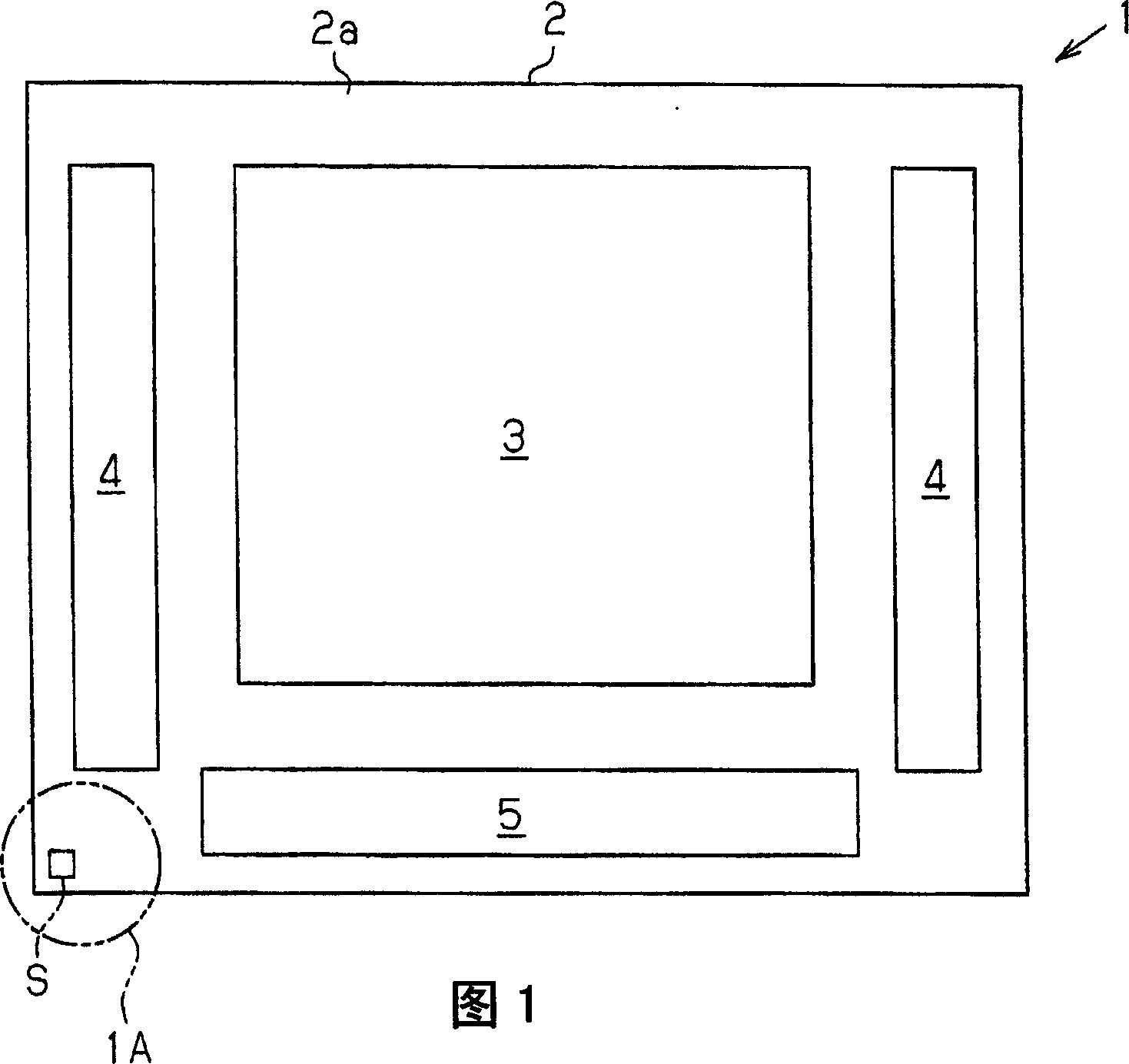
[0022] In FIG. 1 , a quadrangular display portion 3 in which liquid crystal molecules are sealed is formed approximately at the center of one side surface (surface 2 a ) of a transparent substrate 2 . A scanning line driving circuit 4 and a data line driving circuit 5 are formed outside the display unit 3 . The liquid crystal display device 1 controls the alignment state of liquid crystal molecules in the display portion 3 based on the scanning signals generated by the scanning line driving circuit 4 and the data signals generated by the data line driving circuit 5 . The liquid crystal display device 1 displays a desired image in the region of the display unit 3 by modulating planar light from an...


PUM


Abstract

A droplet ejection apparatus has a droplet ejection head, a laser radiation device, and a suction device. The droplet ejection head ejects droplets of liquid onto a target. The laser radiation device radiates laser beams onto an area on the target opposed to the droplet ejection head. The suction device is provided between the laser radiation device and a radiating position on the target at which the laser beams are radiated, and draws elements that have evaporated from the droplets.

Description

technical field [0001] The present invention relates to a droplet ejection device. Background technique [0002] Conventionally, a display device such as a liquid crystal display device or an electroluminescent display device has a substrate for displaying an image. An identification code (for example, a two-dimensional code) indicating manufacturing information including its manufacturing plant or product number is formed on such a substrate for the purpose of quality control or manufacturing management. The identification code is composed of a plurality of dots arranged to form a predetermined pattern. As a manufacturing method for the identification code, JP-A-11-77340 proposes a laser sputtering method in which a metal foil is irradiated with a laser and sputters spots into a film, and JP-A-2003-127537 proposes injecting water containing a polishing material into A water jet method in which dots are printed on the substrate by spraying the substrate or the like. [00...

Claims


Application Information

Patent Timeline
IPC IPC(8): B41J2/01B41J3/407
Inventor 三浦弘纲
Owner SEIKO EPSON CORP
Why Eureka
Try Eureka