
Micro-geometric sense measuring device based on nano-measuring machine and micro-tactometering head

A technology of nano measuring machine and measuring device, which is applied in the direction of measuring device, electromagnetic measuring device, and the measurement of the change force of optical properties of materials when they are stressed, which can solve the interference of measurement environment, cannot realize three-dimensional measurement, and cannot meet Micro-nano processing technology measurement requirements and other issues, to achieve the effect of improving the accuracy of measurement

Inactive Publication Date: 2007-06-06
TIANJIN UNIV
View PDF0 Cites 35 Cited by
  • Summary
  • Abstract
  • Description
  • Claims
  • Application Information

AI Technical Summary

Problems solved by technology

At the same time, optical methods cannot measure certain specific three-dimensional topography, such as the aperture at the edge of the object, the directionality and related dimensions of the surface of the object, etc., so it cannot achieve true three-dimensional measurement
Scanning probe technology represented by atomic force microscope and scanning tunneling microscope uses microscopic effects to detect and control the magnitude of microcurrent and microforce on the tip of the sample and the surface of the sample, and scan the surface of the sample to obtain the morphology and surface characteristics of the sample. Level resolution, but it is easily disturbed by the measurement environment, and thus has a greater impact on the measurement results. At the same time, the measurement range of scanning probe microscopy is only a few tens of microns, which greatly limits the samples for microstructure measurement. In addition, special structures such as microstructures with large aspect ratios cannot be measured
Coordinate measurement technology is to use the traditional coordinate measuring machine as the measurement platform, combined with trigger or analog probe to detect the workpiece under test, but the detection accuracy of traditional coordinate measurement technology can only reach microns or hundreds of nanometers, which can no longer satisfy Measurement requirements for rapid development of micro-nanofabrication technology

Method used


Image

  • Micro-geometric sense measuring device based on nano-measuring machine and micro-tactometering head
  • Micro-geometric sense measuring device based on nano-measuring machine and micro-tactometering head
  • Micro-geometric sense measuring device based on nano-measuring machine and micro-tactometering head

Examples


Embodiment Construction

[0038] The micro geometric measurement device based on the nano measuring machine and the micro tactile probe of the present invention will be described in detail below in conjunction with the embodiments.

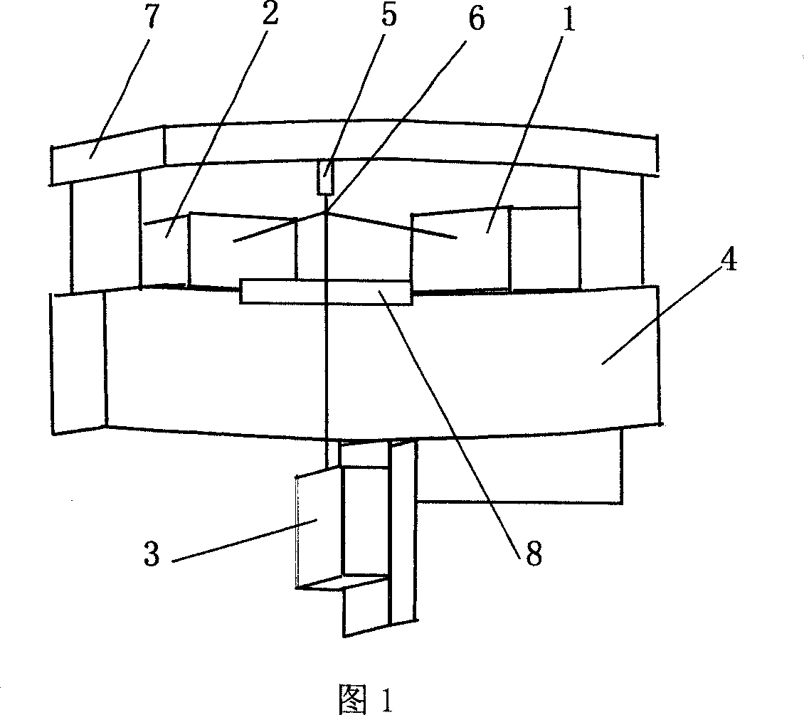
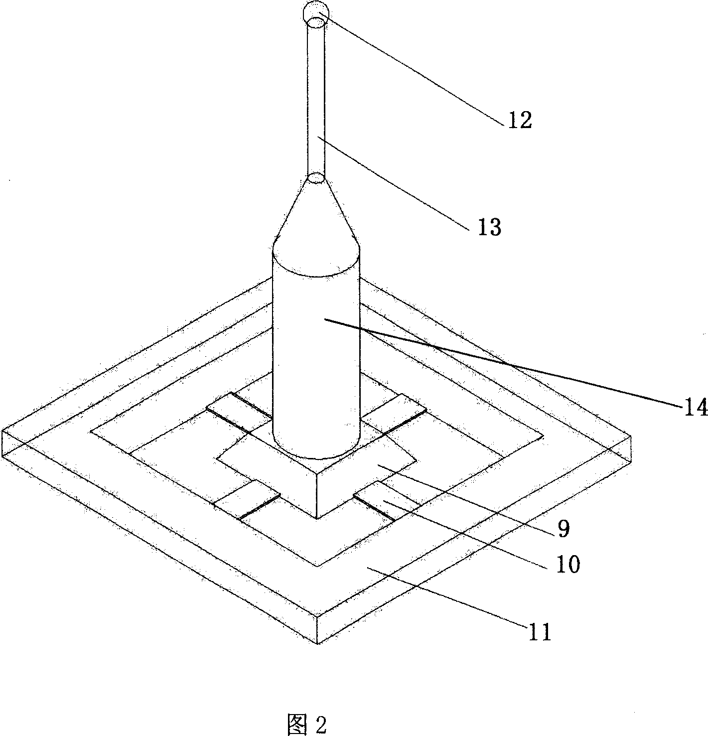
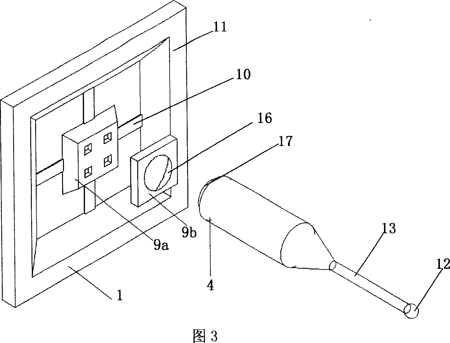
[0039] The micro-geometry measurement device based on the nanometer measuring machine and the micro-tactile probe of the present invention includes the nanometer measuring machine as a positioning measurement platform, and is also provided with a piezoresistive detection system capable of measuring the geometric quantities of micro devices and microstructures. The micro-tactile measuring head system 5 is fixed on the upper part of the nano-measuring machine through the fixing bracket 7 arranged on the upper part of the nano-measuring machine.

[0040] As shown in Figure 1, the described nanometer measuring machine as the positioning measurement platform is a nanometer measuring machine with high precision and wide range, including: an electric control part; a glass stage 8 ...


PUM


Abstract

This invention disclosed a measuring equipment which consists of a nanometer measuring machine and a tiny feeling gauge head. The feeling gauge head was fixed on the machine by a plank. The measuring range of scanning probe micro-technique was improved by this equipment, the range of object by other measuring means was widened; it could manage to measure some micro-geometric senses including dimension, displacement, etc. The measuring precision was improved by this equipment.

Description

technical field [0001] The invention relates to the field of micro-nano testing. In particular, it relates to a micro-geometric quantity measurement device based on a nanometer measuring machine and a micro-tactile probe, which can realize the measurement and characterization of microstructure geometric quantities including parameters such as microforce, displacement, size, and shape features. Background technique [0002] With the rapid development of micro-nano processing technology in recent years, the feature size of the device and its associated tolerances have been continuously reduced, while the complexity of its shape and structure has continued to increase, which puts forward higher requirements for the detection methods of geometric quantities in the processing process. . In the semiconductor industry, the required device detection accuracy has reached the submicron or nanometer level, and the range of detection objects has also expanded to micro devices with spec...

Claims


Application Information

Patent Timeline
Patent Type & Authority Applications(China)
IPC IPC(8): G01B11/00G01B11/02G01B11/24G01B9/02G01B7/00G01B7/02G01B7/28G01L1/14G01L1/18G01L1/24G01N13/16G01N13/12
Inventor 栗大超李源赵大博傅星胡小唐
Owner TIANJIN UNIV
Learn More