System for transmitting control signal by internal IC bus

An internal integrated circuit and control signal technology, applied in the direction of electrical digital data processing, instruments, etc., can solve the problems of microcontroller consumption, multiple pins, and increased component costs

Inactive Publication Date: 2007-06-20
INNOCOM TECH SHENZHEN +1
View PDF0 Cites 6 Cited by
  • Summary
  • Abstract
  • Description
  • Claims
  • Application Information

AI Technical Summary

Problems solved by technology

[0005] In order to overcome the defects of the prior art that the more peripheral devices controlled by the control system using the internal integrated circuit bus to transmit control signals, the microcontroller consumes more pins and increases the cost of c

Method used


Image

  • System for transmitting control signal by internal IC bus

Examples


Embodiment Construction

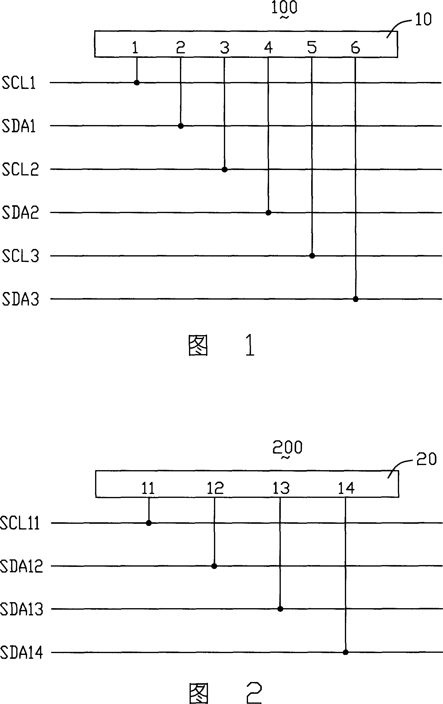
[0010] Please refer to Fig. 2, it is the adoption I of the present invention 2 Schematic diagram of the control system structure for C-BUS transmission of control signals. The control system 200 includes a microcontroller 20 , a clock line SCL11 , a first data line SDA12 , a second data line SDA13 and a third data line SDA14 . The microcontroller 20 includes four pins, the first pin 11, the second pin 12, the third pin 13 and the fourth pin 14 are respectively connected with the clock line SCL11, the first data line SDA12, the second data line SDA13 It is connected with the third data line SDA14. The first pin 11 and the second pin 12 of the microcontroller 10 provide the first clock signal and the first control signal to the controlled first peripheral device (not shown in the figure) respectively through the clock line SCL11 and the first data line SDA12 ). The first pin 11 and the third pin 13 of the microcontroller 20 provide a second clock signal and a second control s...


PUM


Abstract

A control system using internal integrated circuit bus transmission to control signal is prepared as setting multiple pin on controller, connecting these pins separately to clock line and multiple data line one by one, providing relevant clock signal and control signal to each controlled peripheral unit with the same address by said controller through each data line and clock line.

Description

【Technical field】 [0001] The invention relates to a control system, in particular to a control system which adopts an internal integrated circuit bus to transmit control signals. 【Background technique】 [0002] Inter Integrated Circuit BUS (Inter Integrated Circuit BUS, I 2 C-BUS) is an on-chip two-wire serial expansion bus proposed by Philips Semiconductors that is widely used in consumer electronics, communications and industrial electronics. I 2 C-BUS is an integrated circuit internal control bus composed of two bidirectional data lines. Its main feature is that only two data transmission paths are required, namely a serial data line (Serial Data Line, SDA) and a serial clock line ( Serial Clock Line, SCL). Every component connected to the bus has a unique address. I 2 C-BUS allows several compatible devices (such as memory, analog / digital converter, digital / analog converter and organic light-emitting diode display driver, liquid crystal display driver, etc.) to shar...

Claims


Application Information

Patent Timeline
IPC IPC(8): G06F13/40
Inventor 高翌翔
Owner INNOCOM TECH SHENZHEN
Why Eureka
Try Eureka