Catalytic combustion evaporator

A catalytic combustion and evaporator technology, applied in combustion chambers, combustion methods, combustion equipment, etc., can solve the problems that cannot meet the requirements of compact and efficient hydrogen production systems, the utilization of waste heat from combustion exhaust gas is not considered, and the efficiency is low. Excellent evaporation effect, reduced heat transfer resistance, uniform distribution effect

Inactive Publication Date: 2007-07-11
DALIAN INST OF CHEM PHYSICS CHINESE ACAD OF SCI
View PDF0 Cites 16 Cited by
  • Summary
  • Abstract
  • Description
  • Claims
  • Application Information

AI Technical Summary

Problems solved by technology

[0005] In the existing methanol reforming hydrogen production technology, a latest patent in the United States (Pub.No: 0046493A1) introduces a catalytic combustion evaporator, but it is only a simple combination of two devices, that is, catalytic burner and The evaporators are combined together, and t

Method used


Image

  • Catalytic combustion evaporator
  • Catalytic combustion evaporator
  • Catalytic combustion evaporator

Examples


Embodiment Construction

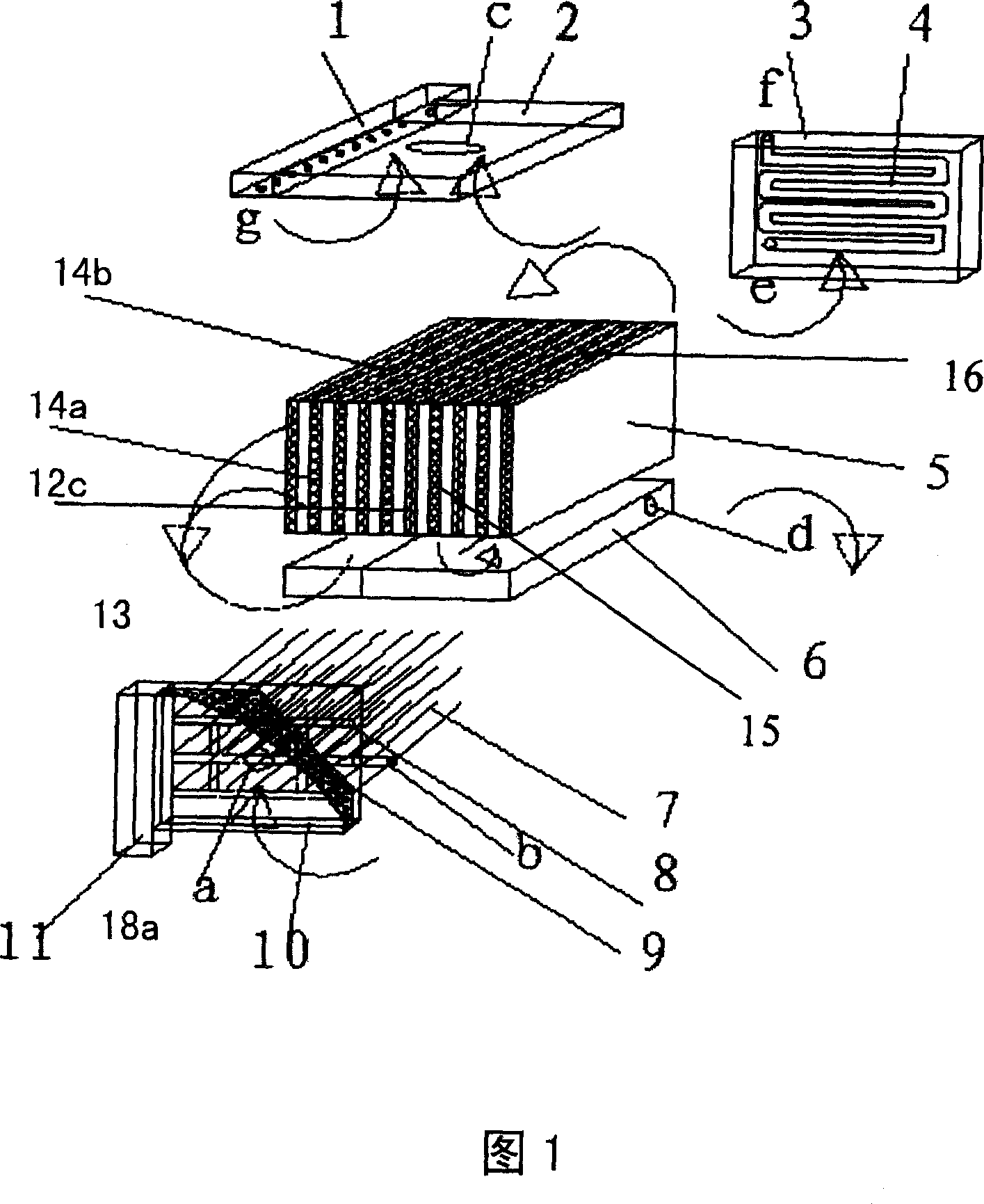
[0025] As shown in Figure 1, it is a catalytic combustion evaporator of the present invention. The catalytic combustion evaporator body 5 is a rectangular body. In the body 5, there are nineteen chambers from left to right, of which ten combustion chambers 12, nine The evaporation chamber 14, the combustion chamber 12 and the evaporation chamber 14 are all flat rectangular cavities, and the cavities are of plate-fin structure to improve the heat transfer film coefficient of the cavities. The combustion chamber 12 is open at the front and rear, and the internal fluid flows in the front and rear direction, with the upper and lower chamber side walls, and the left and right heat conduction plates 15; 16. The combustion chamber 12 and the evaporation chamber 14 are arranged alternately, and are in close contact with each other through the heat conduction plates 15 and 16, and the fluids in the two adjacent chambers flow in cross-flow. The combustion chamber 12 forms ten parallel p...


PUM


Abstract

The invention relates to a catalytic combustion heat exchanger. The main body is plate-fin structure and is constituted by welding with several head plate. The flow of logistics between combustor and evaporator is cross-flow and cavities are isolated by heat-conducting plate. Catalytic combustion reaction between combustible gas and air happens in the combustor to discharge mass heat energy and most of heat energy is transferred to the steam cavity through heat-conducting plate. The invention is provided with mild reaction temperature of catalytic combustion, high energy efficiency, very small pollution and friendship to circumstance. It is also provided with stable running, easy operation and compact structure. By parallel treatment of multiple cells evaporation capacity is expanded. The catalytic combustion heat exchanger, as civil hot water supply device, has a potential meaning. The catalytic combustion heat exchanger is widely applied in coupling reaction system of strong reaction heat and suction heat, and the process where reaction objects are pretreated. It is especially applied in preheating and steaming of liquid stock in fuel battery hydrogen production system, field hydrogen production system and hydrogen production of concentrated scale station.

Description

technical field [0001] The invention relates to a catalytic combustion evaporator. The catalytic combustion evaporator has potential significance as a civil hot water device; the catalytic combustion evaporator can also be widely used in a coupled reaction system with strong heat release and heat absorption, and it is necessary to carry out the reaction on the reactants. In the process of pre-evaporation, it is especially suitable for preheating and gasification of raw materials in fuel cell hydrogen production systems, on-site hydrogen production systems and centralized scale station hydrogen production systems. Background technique [0002] At present, equipment requirements tend to be compact, safe, efficient and environmentally friendly, and the new design concept of process intensification has attracted widespread attention. The catalytic combustion evaporator is produced based on this design concept. Its catalytic combustion reaction temperature is mild, its energy eff...

Claims


Application Information

Patent Timeline
IPC IPC(8): F28D9/02F23C6/02
Inventor 王树东李世英潘立卫王胜袁中山
Owner DALIAN INST OF CHEM PHYSICS CHINESE ACAD OF SCI
Why Eureka
Try Eureka