Hybrid vehicle and method of controlling the same

a hybrid vehicle and control method technology, applied in the direction of propulsion parts, machines/engines, gas pressure propulsion mounting, etc., can solve the problems of insufficient regeneration control of filters and increased internal resistance, and achieve the effect of reducing the influence of charging/discharging efficiency, increasing the internal resistance of batteries, and reducing the influence of internal resistan

Active Publication Date: 2018-06-26
TOYOTA JIDOSHA KK
View PDF26 Cites 4 Cited by
  • Summary
  • Abstract
  • Description
  • Claims
  • Application Information

AI Technical Summary

Benefits of technology

[0008]As the battery temperature decreases, the internal resistance of the battery tends to increase. Therefore, when the battery is in a low-temperature condition in winter or in cold regions, for example, joule loss due to the internal resistance increases. Therefore, the charging / discharging efficiency is reduced as compared with the case where the battery temperature is in a relatively high condition. Accordingly, in a battery installed on a hybrid vehicle, charge / discharge electric power (charge power or discharge power) is restricted, so as to reduce an influence of reduction of the charging / discharging efficiency in the case where the battery is in a low-temperature condition.
[0017]With the above arrangement, the threshold value is set to the temperature at which the electrical storage device becomes able to supply electric power used by the rotating electric machine for driving the internal combustion engine (for example, electric power needed for motoring control). When the temperature of the electrical storage device is lower than the threshold value, the electrical storage device is warmed up until the temperature of the electrical storage device exceeds the threshold value; therefore, restrictions on the discharge power are reduced, and the motoring control can be performed using the rotating electric machine. As a result, the filter regeneration control can be carried out.
[0019]With the above arrangement, when the internal combustion engine is controlled (output level elevation control) so as to increase the output of the engine to a level higher than that required for moving the vehicle, for example, the threshold value is set to the temperature at which the electrical storage device can be charged with electric power corresponding to the amount of increase of the output. When the temperature of the electrical storage device is lower than the threshold value, the electrical storage device is warmed up until the temperature of the electrical storage device exceeds the threshold value; therefore, restrictions on the charge power are reduced, and the electrical storage device can be charged with electric power generated by the rotating electric machine. As a result, the filter regeneration control can be carried out.
[0021]With the above arrangement, the electrical storage device is warmed up to a temperature level that is higher than the threshold value, so that a margin for the threshold value can be secured. Therefore, even if warm-up of the electrical storage device is finished, the charge power or discharge power from the electrical storage device is less likely to be restricted until the temperature of the electrical storage device is reduced down to the threshold value.
[0023]With the above arrangement, the electrical storage device is warmed up to the larger one of the reference value and the threshold value; therefore, the filter regeneration control can be performed with ease or reliability until the temperature of the electrical storage device is reduced to the smaller one of the reference value and the threshold value.

Problems solved by technology

Therefore, when the battery is in a low-temperature condition in winter or in cold regions, for example, joule loss due to the internal resistance increases.
As a result, regeneration control of the filter may not be sufficiently performed.

Method used


Image

  • Hybrid vehicle and method of controlling the same
  • Hybrid vehicle and method of controlling the same
  • Hybrid vehicle and method of controlling the same

Examples


first embodiment

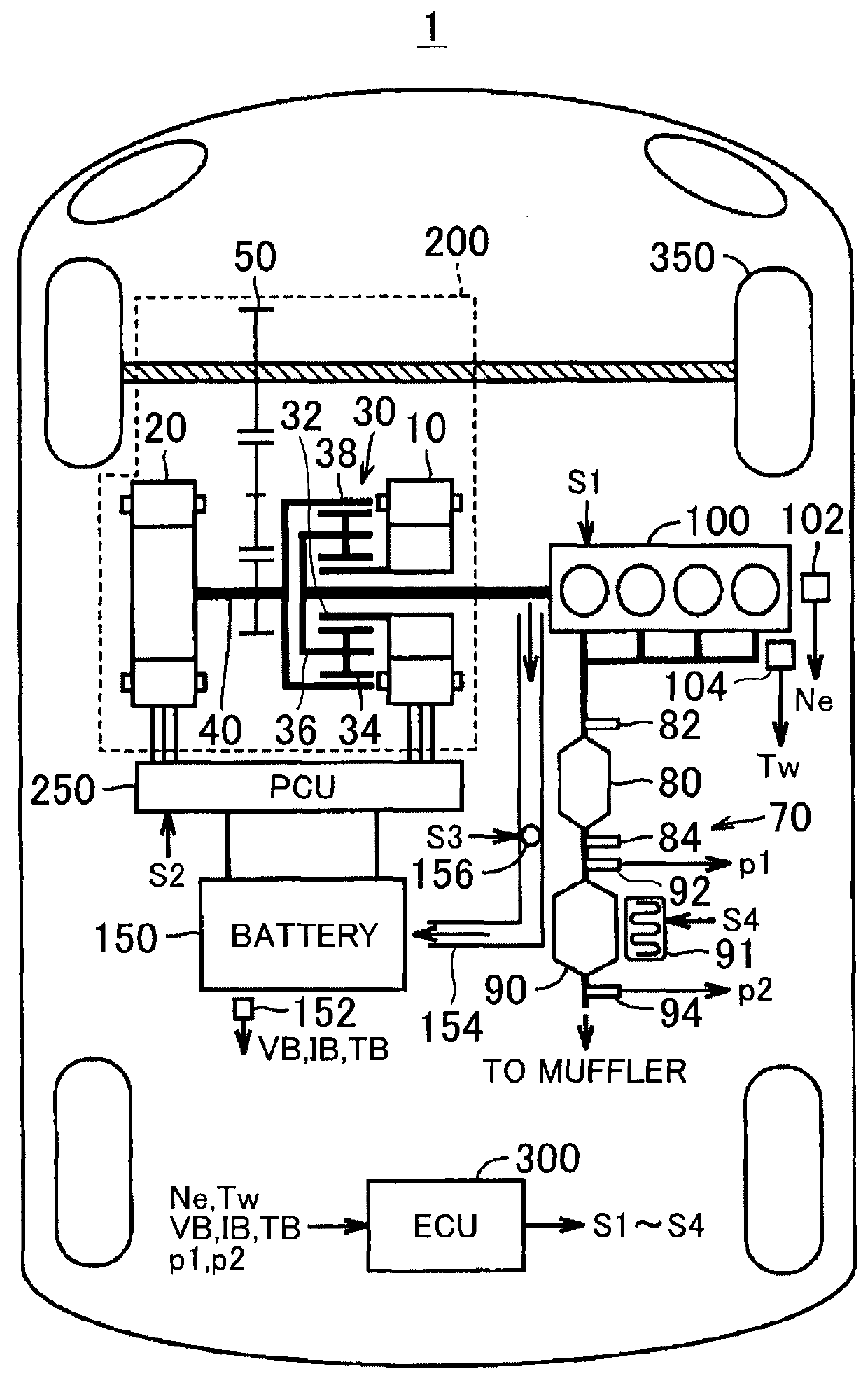
[0038]FIG. 1 is a block diagram schematically showing the configuration of a vehicle according to the invention. Referring to FIG. 1, the vehicle 1 is a hybrid vehicle. The vehicle 1 includes an engine 100, a battery 150, a transmission 200, a PCU (Power Control Unit) 250, an ECU (Electronic Control Unit) 300, and drive wheels 350.

[0039]The engine 100 (internal combustion engine) generates driving force for moving the vehicle 1, according to a control signal 51 from the ECU 300. In this embodiment, a gasoline engine is employed as the engine 100. However, the fuel of the engine 100 is not limited to gasoline, but may be light oil (diesel fuel), biofuel (such as ethanol), or gas fuel (such as propane gas), for example.

[0040]A crank position sensor 102 is provided at a position opposed to a crankshaft (not shown) of the engine 100. The crank position sensor 102 detects the rotational speed Ne of the engine 100 (which will also be called “engine speed”), and outputs the detection resul...

second embodiment

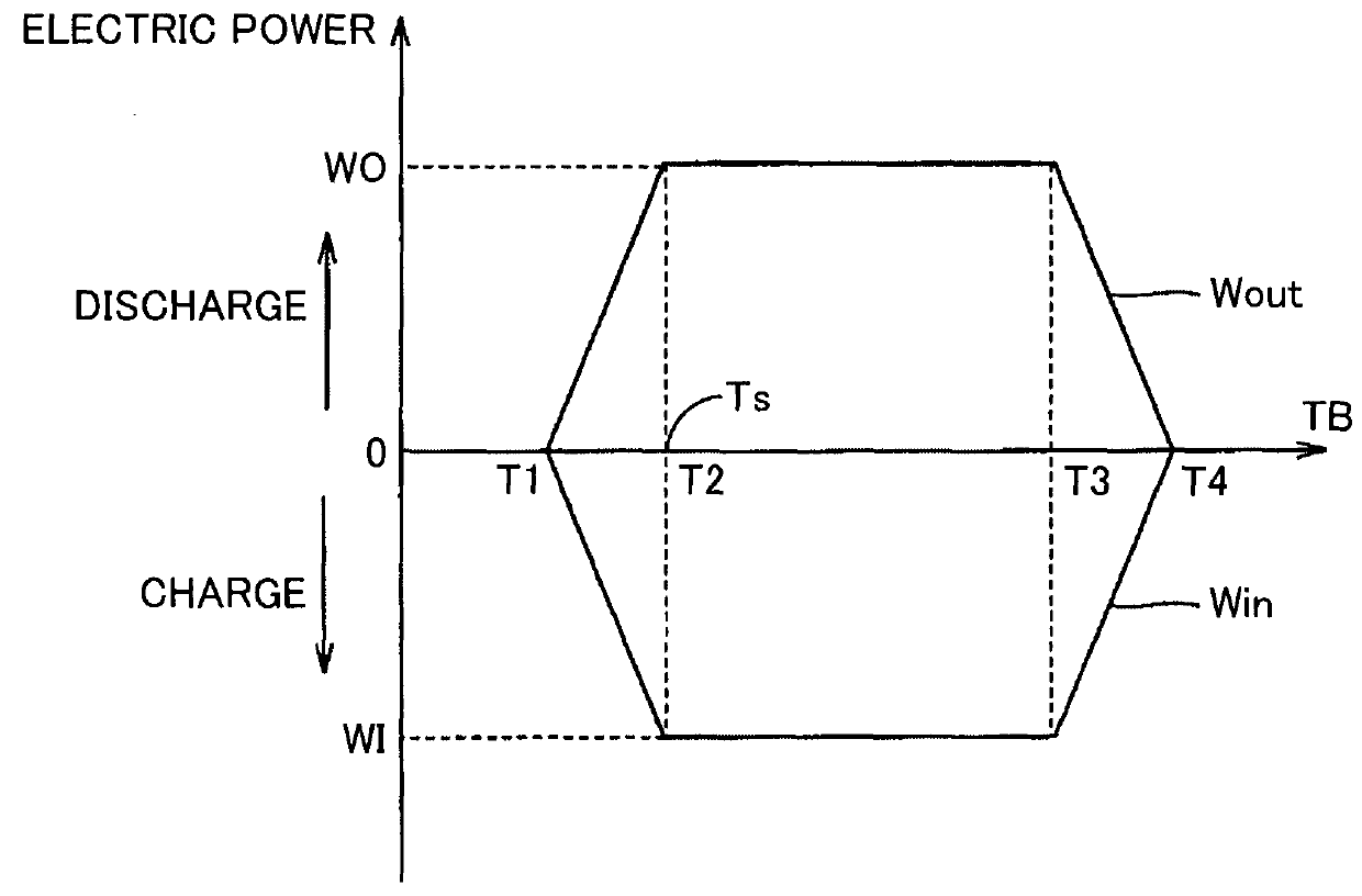
[0106]Thus, when the reference value Ts is set to a value different from the temperature T2, too, the battery can be warmed up until the GPF regeneration control becomes able to be carried out. Since a margin for the temperature T2 can be secured by warming up the battery to a temperature level higher than the temperature T2, the charge power or discharge power is less likely to be restricted even when the battery temperature TB is lowered during execution of the GPF regeneration control.

[0107]The temperature T2 is specified so as to protect the battery by restricting the charge power and the discharge power, and is a fixed value that is determined according to the specifications of the battery. On the other hand, the reference value Ts is specified so as to secure the charge power or discharge power needed for execution of the GPF regeneration control. Therefore, the reference value Ts can be changed according to a method of executing the GPF regeneration control (which (one) of t...

third embodiment

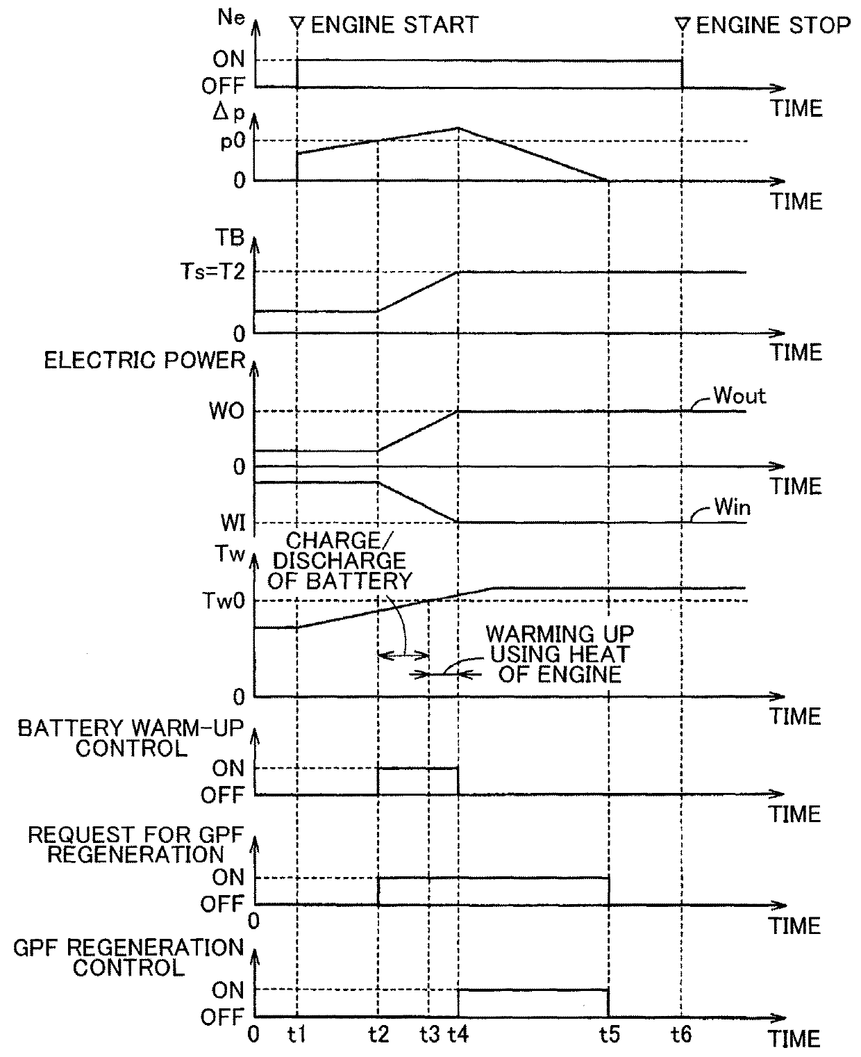
[0109]FIG. 9 is a timing chart useful for explaining the battery warm-up control according to the While the reference value Ts may be larger than the temperature T2 or smaller than the temperature T2, depending on the manner of setting the reference value Ts, the case where the reference value Ts is set to be smaller than the temperature T2 will be described in FIG. 9. Referring to FIG. 9, control before time t3 is substantially the same as control before time t3 in the timing chart shown in FIG. 3, and therefore, will not be repeatedly described.

[0110]At time t3a, the battery temperature TB exceeds the reference value Ts. This indicates that the battery 150 is warmed up to a battery temperature TB at which the GPF regeneration control can be performed. However, since the battery temperature TB is lower than the temperature T2, the charge power and discharge power of the battery 150 are restricted. Therefore, in this embodiment, the battery warm-up control is continued so that the ...


PUM

PropertyMeasurementUnit
temperatureaaaaaaaaaa
electric poweraaaaaaaaaa
temperatureaaaaaaaaaa

Abstract

A hybrid vehicle includes an internal combustion engine, a filter, an electrical storage device, a rotating electric machine, and a controller. The filter is configured to trap particulate matter in exhaust gas of the internal combustion engine. The rotating electric machine is configured to generate electric power using power from the internal combustion engine so as to charge the electrical storage device, and drive the internal combustion engine using electric power from the electrical storage device. The controller is configured to control the internal combustion engine and the rotating electric machine, so as to warm up the electrical storage device when regeneration control needs to be performed and when the temperature of the electrical storage device is lower than a reference value. The regeneration control is control for raising the temperature of the filter to a predetermined temperature so as to burn the particulate matter. The controller may be configured to execute the regeneration control when the temperature of the electrical storage device exceeds the reference value.

Description

CROSS-REFERENCE TO RELATED APPLICATIONS[0001]This application is a national phase application of International Application No. PCT / IB2015 / 000323, filed Mar. 13, 2015, and claims the priority of Japanese Application No. 2014-054864, filed Mar. 18, 2014, the content of both of which is incorporated herein by reference.BACKGROUND OF THE INVENTION[0002]1. Field of the Invention[0003]The invention relates to a hybrid vehicle and a method of controlling the hybrid vehicle. In particular, the invention relates to a hybrid vehicle including a filter for trapping particulate matter in exhaust gas of an internal combustion engine, and a method of controlling the hybrid vehicle.[0004]2. Description of Related Art[0005]Exhaust gas emitted from an engine contains particulate matter (which will also be referred to as “PM”). It is preferable not to emit the PM into the atmosphere since the PM may exert an influence on the environment, or the like. Therefore, a filter for trapping the PM may be ins...

Claims


Application Information

Patent Timeline
Patent Type & Authority Patents(United States)
IPC IPC(8): B60W20/16B60K6/44B60L11/18B60K6/445B60W10/06B60W10/08B60W20/00F02D41/02H01M10/615H01M10/44H01M10/48H01M10/625H01M10/63B60W20/13F01N3/027B60W10/26H01M10/6564F02D37/02
CPCB60W20/16B60L11/1875B60W10/06B60W10/08B60W10/26B60W20/00B60W20/13F01N3/027F02D41/029F02D41/0245H01M10/443H01M10/486H01M10/615H01M10/625H01M10/63B60K6/445Y10S903/93B60L2240/545B60W2510/068B60W2510/246B60W2530/12B60W2710/0694B60W2710/246B60Y2300/476F02D37/02F02D2041/026F02D2200/503H01M10/6564H01M2220/20Y02T10/26Y02T10/54Y02T10/6239Y02T10/705Y02T10/7005B60L58/27B60K6/365Y02T10/12Y02T10/40Y02T10/62Y02T10/70Y02E60/10
Inventor NAWATA, HIDEKAZUINOUE, TOSHIOFUKUI, KEITAHONDA, TOMOAKINIWA, YUTAOSAWA, TAICHI
Owner TOYOTA JIDOSHA KK
Why Eureka
Try Eureka