Semiconductor device
a technology of semiconductor devices and semiconductors, applied in semiconductor devices, solid-state devices, transistors, etc., can solve the problems of increasing recovery loss, reducing recovery capability, and inability to stop the flow of holes, so as to improve recovery characteristics
- Summary
- Abstract
- Description
- Claims
- Application Information
AI Technical Summary
Benefits of technology
Problems solved by technology
Method used
Image
Examples
first embodiment
[0038]A first embodiment of the present disclosure will be described. Note that a semiconductor device of the present embodiment is suited for use as a power switching device employed in a power supply circuit such as an inverter or a DC / DC converter.
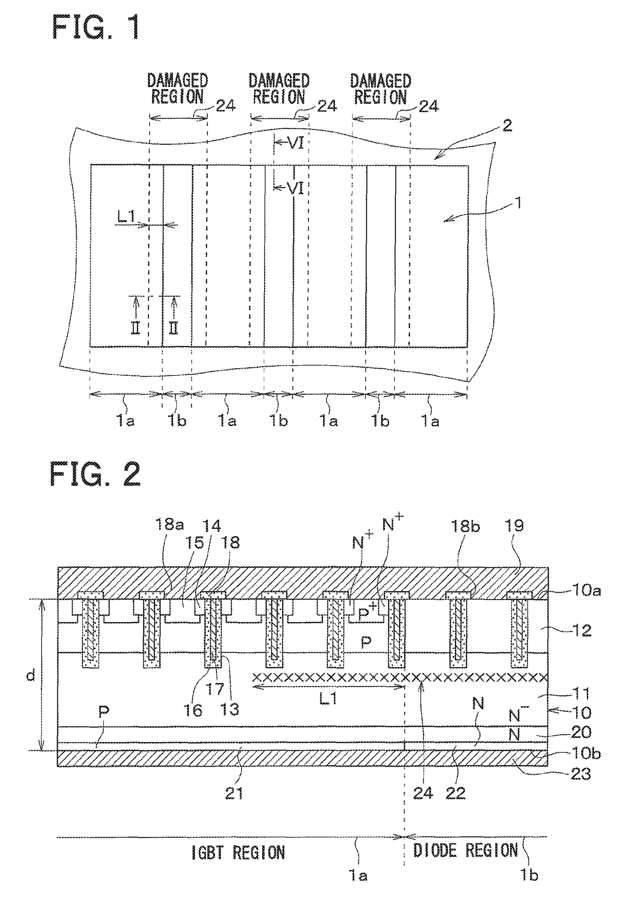
[0039]As illustrated in FIG. 1, the semiconductor device includes a cell region 1 and a periphery region 2 surrounding the cell region 1.
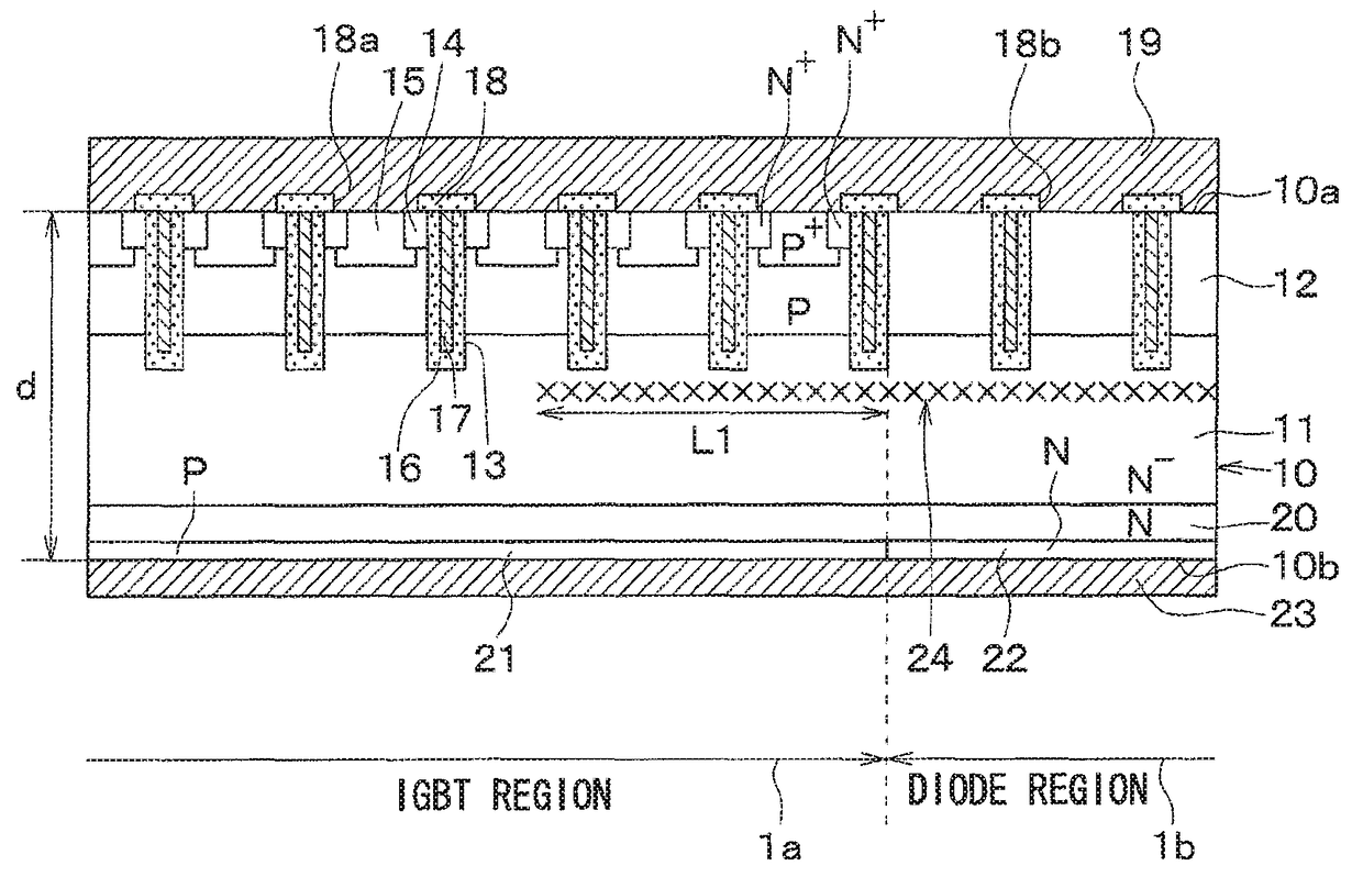
[0040]An IGBT region 1a in which an IGBT device is formed and a diode region 1b in which a diode device is formed are alternately formed in the cell region 1, as illustrated in FIGS. 1 and 2.
[0041]Specifically, the IGBT region 1a and the diode region 1b (cell region 1) are formed on an N−-type semiconductor substrate 10 functioning as a drift layer 11. The IGBT region 1a and the diode region 1b extend along one direction (vertical direction with respect to FIG. 1) of one surface 10a of the semiconductor substrate 10 and are formed alternately in a direction orthogonal to the direction of extension.
[004...
second embodiment
[0077]A second embodiment of the present disclosure will be described. Unlike the first embodiment, a damaged region 24 is also formed in a periphery region 2 in the present embodiment. The rest is similar to the first embodiment and thus will not be described.
[0078]As illustrated in FIGS. 10 and 11, the damaged region 24 formed in a diode region 1b extends into the periphery region 2 in the present embodiment. As a result, holes (excess carriers) in a drift layer 11 in the periphery region 2 recombine with the damaged region 24 formed in the periphery region 2 and vanish, whereby injection of the holes from the periphery region 2 into the diode region 1b can be prevented.
[0079]The relationship between the damaged region 24 formed in the periphery region 2 and the thickness of a semiconductor substrate 10 will now be described. In the following description, the width of the damaged region 24 formed in the periphery region 2 is denoted as L2, and the width of the damaged region 24 fo...
third embodiment
[0085]A third embodiment of the present disclosure will be described. The shape of a damaged region 24 of the present embodiment is modified from that of the second embodiment. The rest is similar to the first embodiment and thus will not be described.
[0086]In the present embodiment, as illustrated in FIG. 14, the width of the damaged region 24 formed in an IGBT region 1a is larger in an area formed on both end sides of the boundary between a diode region 1b and the IGBT region 1a than in an area formed at the center between both ends. Specifically, the width (length in a horizontal direction with respect to FIG. 14) of the area formed on both end sides of the boundary with the diode region 1b in the IGBT region 1a is denoted as L2.
[0087]As a result, injection of holes from the periphery region 2 into the diode region 1b through the IGBT region 1a can be prevented and, at the same time, recovery characteristics of the diode region 1b can be improved.
[0088]Note that when such a semic...
PUM
 Abstract
Description
Claims
Application Information
 - R&D
- Intellectual Property
- Life Sciences
- Materials
- Tech Scout
- Unparalleled Data Quality
- Higher Quality Content
- 60% Fewer Hallucinations
Browse by: Latest US Patents, China's latest patents, Technical Efficacy Thesaurus, Application Domain, Technology Topic, Popular Technical Reports.
© 2025 PatSnap. All rights reserved.Legal|Privacy policy|Modern Slavery Act Transparency Statement|Sitemap|About US| Contact US: help@patsnap.com


