Dual weld plug for an electrochemical cell

a technology of electrochemical cells and fill covers, which is applied in the direction of cell components, batteries, conductors, etc., can solve the problems of compromising the robustness of the hermetic seal, insufficient to prevent potential leakage of electrolyte, and inconvenient to use, so as to reduce the diameter, reduce the effect of localized heating and increasing the opening depth

Active Publication Date: 2018-10-23
WILSON GREATBATCH LTD
View PDF8 Cites 20 Cited by
  • Summary
  • Abstract
  • Description
  • Claims
  • Application Information

AI Technical Summary

Benefits of technology

[0013]Accordingly, the present invention is directed to an electrochemical cell having an electrolyte fill port opening comprising a discontinuous opening with at least two welded sealing members positioned at differing depths within the fill port. The fill port opening is designed such that its diameter decreases with increasing opening depth into the cell. Such a smaller diameter within the cell further minimizes localized heating and reduces the possibility of electrolyte expulsion. In addition, the electrochemical cell comprises plate electrodes that are housed inside mating “clamshell” casing components. A lid or header assembly design is generally used in conjunction with the clamshell case, the lid containing both a hermetic glass-to-metal seal for a terminal lead, and a filling port.
[0014]A first sealing member is preferably positioned within the opening at a position between the top and bottom surfaces of the electrolyte fill port. The first sealing member is welded in position within the fill port using a first energy. A second sealing member is positioned within the opening at a distance away from the first sealing member and closer to the exterior opening of the fill port, i.e. the top surface of the lid or header. The second sealing member is welded into position at a welding energy that is greater than the welding energy used to weld the first sealing member. A lower welding energy is selected to close the first sealing member within the fill port opening and minimize localized heating of the electrolyte material that would result in electrolyte expulsion.
[0015]If more than two sealing members are positioned within the opening of the fill port, each additional sealing member is positioned a distance away from the previous sealing member and closer to the upper surface of the opening. These additional sealing members are welded into position using a welding energy that is about equal to, or greater than the welding energy used to seal the first sealing member. The first sealing member is positioned furthest away from the top or exterior surface of the header or cell sidewall. The electrolyte fill port is designed such that the innermost sealing member is welded using parameters that prevent leaking of the electrolyte. The second, third and fourth sealing members are welded into position such that a hermetic seal is created. The shape of the sealing member is non-limiting and may comprise a plate, a sphere or a plug. The sealing members are dimensioned such that they fit within the diameter of the fill port opening.
[0016]Each of the sequential sealing members is preferably welded utilizing different welding parameters. The inner most sealing member is welded into place utilizing a lesser amount of energy than subsequently welded sealing members that are positioned closer to the exterior opening of the fill port residing at the top surface of the header. Thus, by welding the inner sealing member in place at a lower energy, the inner sealing member is positioned within the fill port opening without the need to mechanically press the sealing member in place. In addition, the lower welding energy creates a seal that minimizes or prevents electrolyte from leaking due to thermal expansion of the cell components. Subsequent sealing members, that are closer to the exterior of the header, can thus be welded in place at increased energies to ensure a hermetic seal without causing electrolyte to expel from within the casing.

Problems solved by technology

However, these electrochemical cells comprising single electrolyte fill covers are not desirable because these cell designs are typically prone to electrolyte leakage during manufacture.
Expelled electrolyte material is not desirable because it generally interacts with the welded material causing discoloration of the weld and may potentially compromise the robustness of the hermetic seal of the electrolyte fill port over time.
However, the applicants of the present invention have discovered that merely pressing such a sealing element within the fill port opening, as disclosed by Paulot, is not sufficient in preventing potential leakage of electrolyte from within the cell during manufacture.
Variations in plug dimensions and surface conditions increase the difficulty in precisely controlling the insertion force of the plug to minimize electrolyte leakage.
In addition, heat from the welding of the sealing element to the case during manufacturing of the cell exacerbates these variations causing a potential break in the temporary seal, which then allows for the electrolyte to leak out from the case.
In addition, during welding of the upper sealing member, heat from the welding process typically expands the components of the cell, thereby possibly additionally compromising the interference fit of the lower sealing member.
As a result, additional electrolyte material may leak out from the casing which may then interact with the welded material of the upper sealing member.
Removal of electrolyte from within the fill port opening is not desirable.
The relatively small diameter of the fill port opening increases the difficulty of electrolyte removal.
The electrolyte removal process increases cost and time of manufacture of the electrochemical cell.
Such a mechanically pressed plug does not adequately stop leakage of electrolyte material during welding of the fill port closure.
Thus, as previously stated, the problem with the prior art lid or header designs is that during the electrolyte fill port enclosure procedure, electrolyte material typically escapes out of the fill port thus resulting in a loss of electrolyte material.
Furthermore, during welding of the fill port opening, heat from the welding causes localized heating of the metallic casing and electrolyte materials.
This localized heating can cause the electrolyte to expel and leak out from within the casing.
Such expulsion of the electrolyte material typically results in discoloration of the welded fill enclosure metal as the electrolyte material interacts with the welded metal.
In addition, such an interaction of the electrolyte material with the fill opening enclosure material, during welding, may result in a change in the microstructure of the welded seal.
Such a change in the weld microstructure may compromise the robustness of the hermetic seal over time.

Method used


Image

  • Dual weld plug for an electrochemical cell
  • Dual weld plug for an electrochemical cell
  • Dual weld plug for an electrochemical cell

Examples


Embodiment Construction

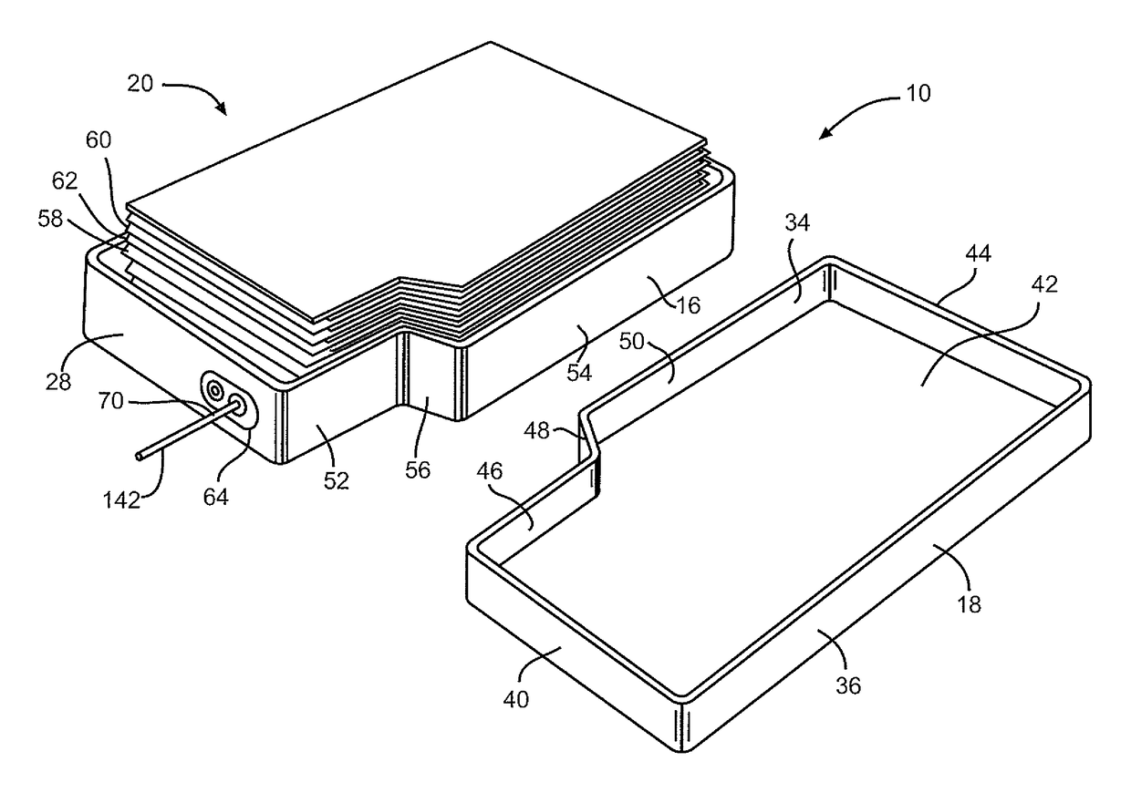
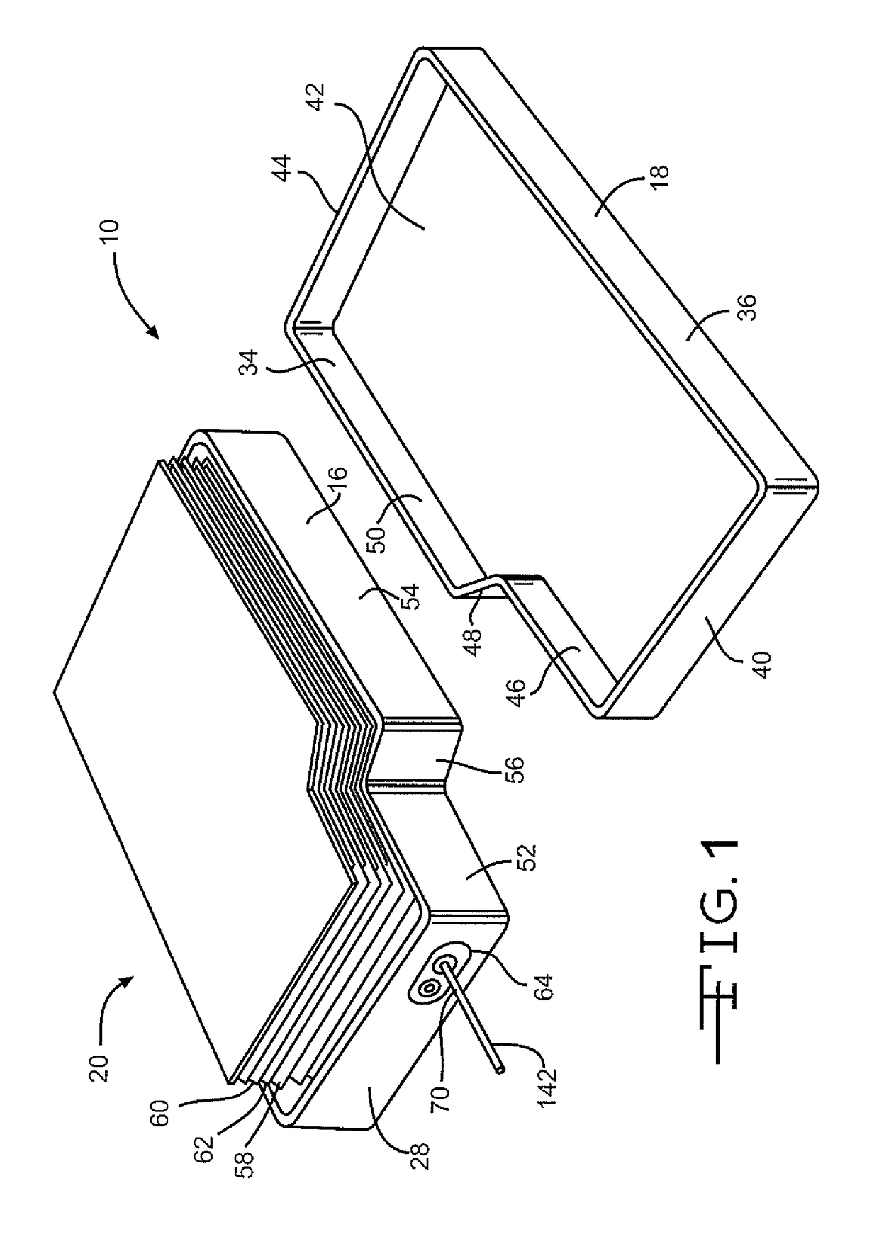
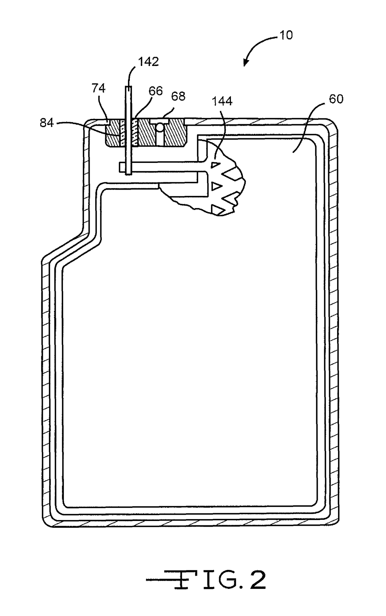
[0031]Turning now to the drawings, FIGS. 1-3 illustrate an embodiment of an electrochemical cell 10 having a header assembly 12 according to the present invention. The header assembly 12, which will be described in detail hereinafter, may comprise a one-piece construction or, alternatively be constructed of a multiple piece subassembly. First, the cell 10 includes a conductive casing of metal 14, such as stainless steel or titanium, having first and second clamshell portions 16 and 18. As shown in FIG. 3, the clamshell portions 16 and 18 are mated together and sealed about their periphery to provide a hermetic enclosure for an electrode assembly 20. The preferred methods of sealing are welding and brazing.

[0032]In particular as shown in FIG. 4, the first clamshell 16 comprises spaced apart sidewalls 22 and 24 extending to and meeting with spaced apart end walls 26 and 28. The sidewalls 22, 24 and the end walls 26, 28 meet each other at curved corners and extend to a front wall 30. O...


PUM

PropertyMeasurementUnit
welding energyaaaaaaaaaa

Abstract

The present invention is directed to an electrochemical cell having plate electrodes housed inside a mating “clamshell” casing. When mated together, the casing components are form-fitting with respect to the internal battery structure so as to reduce the overall size of the electrochemical package. A header assembly containing both a glass-to-metal seal opening for a terminal lead and an electrolyte fill opening is used in conjunction with the clamshell casing. The electrolyte fill opening is constructed with an elongated opening with at least two different radii. A first and second sealing element is welded within the electrolyte fill opening at different depths within the header to block the flow of electrolyte and form a hermetic seal.

Description

BACKGROUND OF THE INVENTION[0001]1. Field of the Invention[0002]The present invention relates to an improvement in an electrochemical cell designed by enhancing the manufacture of a housing of the cell, particularly the closure of a fill port. The fill port is used to introduce an electrolyte into the housing of the electrochemical cell.[0003]2. Prior Art[0004]In prior and current product lines, the design of electrochemical cells includes a lid with separate ferrules or openings for providing a terminal pin feedthrough, and an electrolyte fill and closure mechanism. Designs for these functions usually consist of a lid, GTMS ferrule, and an electrolyte fill ferrule which are welded together to form a subassembly. This subassembly is further manufactured by having the GTMS inserted into its ferrule and the completed assembly is then welded into a battery case of various configurations. The battery is filled with electrolyte via the fill ferrule or area, and the fill mechanism compris...

Claims


Application Information

Patent Timeline
Patent Type & Authority Patents(United States)
IPC IPC(8): H01M2/36H01M2/06H01M10/0525H01M6/04B23K26/211H01M2/02B23K101/38B23K103/00B23K103/18H01M50/103H01M50/627
CPCH01M2/367H01M2/024H01M2/0207H01M2/065H01M2/361H01M2/362H01M6/045H01M10/0525B23K26/211B23K2101/38H01M2220/10H01M2220/20H01M2220/30H01M2300/0014B23K2103/18B23K2103/54Y02E60/10H01M50/103H01M50/186H01M50/191H01M50/627H01M50/668
Inventor DAI, XIANGYANGFREITAG, GARYGRUBB, KENNETH L.HALLIFAX, PAUL T.ROY, MARK J.SERPE, LOU
Owner WILSON GREATBATCH LTD
Why Eureka
Try Eureka