Self-excitation push-pull type converter

a push-pull converter and self-excitation technology, which is applied in the direction of dc-dc conversion, power conversion systems, fixed transformers, etc., can solve the problems of increasing copper loss, reducing instead of increasing the conversion efficiency of the converter, and difficult to select between these parameters. , to achieve the effect of improving efficiency, reducing the number of coil turns, and improving the efficiency of the self-excitation push-pull converter

Active Publication Date: 2018-11-06
MORNSUN GUANGZHOU SCI & TECH
View PDF10 Cites 1 Cited by
  • Summary
  • Abstract
  • Description
  • Claims
  • Application Information

AI Technical Summary

Benefits of technology

[0037]Therefore, the technical issue to be solved by this invention is to overcome the disadvantages of the existing self-excitation push-pull converters, so that the efficiency of the self-excitation push-pull converter can be substantially improved when the converter is used with light loads; its efficiency can be further improved when used at rated load, the number of turns of the coils on the magnetic saturated transformers in the self-excitation push-pull converter can be reduced; and the working frequency of the self-excitation push-pull converter can be increased while maintaining its loss at a relatively low level. It will also reduce the current spikes appearing when the self-excitation push-pull converter conducts or is cut off, to further increase the efficiency while lowering the output ripple.

Problems solved by technology

In converter products today, magnetic cores with extremely high working magnetic induction intensity Bw have been selected, the number of coil turns N increased, resulting in increased copper loss; the increase of the effective sectional area S of magnetic core also increases the loss each time when it approaches or enters the magnetic core magnetic saturation, thus reducing instead of increasing the conversion efficiency of the converter.
Therefore, in the design of a self-excitation push-pull converter, it is quite difficult to select between these parameters.
To increase the conversion efficiency of the Jensen circuit, for the similar reasons, if the effective sectional area S of the magnetic core of the small transformer B1 is too small, the pushing power will be insufficient, the switching transistor cannot become well saturated and conducting, resulting in increased voltage drop loss and reduced converter conversion efficiency.
When the effective sectional area S of the magnetic core of the small transformer B1 is taken too high, the self-loss will also be high.
Of course, the problem insufficient pushing power can be solved by increasing the number of turns N of the coil, but it also results in the following process problem: with increased number of turns N, as the small transformer B1 must work under magnetic saturation state and no air gap can be made, it will make the winding highly difficult.
3. when the Input Voltage is High, there are Many Turns on Transformer B1, Making the Processing Quite Difficult.
When a machine is used, when the first layer is finished, it is quite difficult to wind the second layer on the first one, as it will break the wire sequence of the first layer, and the winding will be made worse and worse.
In manual winding, it is quite difficult to avoid one or two turns more or less as the number of turns must be memorized entirely by workers, if the number of turns is different, deviation will occur in the output voltage, and in a serious case, the original function cannot be realized when the transformer is installed.
Therefore, in the industrial field and market today, it is difficult to find self-excitation push-pull converter modules with working voltage of 48V and over, and also for this reason, the efficiency has to be reduced for less number of turns.
4. it is Difficult to Increase the Working Frequency
As the self-excitation push-pull converter circuit performs each push-pull operation by the magnetic core approaching or reaching magnetic saturation, therefore, when the working frequency increases, its loss will increase and conversion efficiency will reduce.
1) The converter efficiency is low with light loads;
2) It is not possible to further increase the efficiency at rated load;
3) When the input voltage is high, there are many turns on transformer B1, making the processing quite difficult;
4) It is difficult to increase the working frequency;
5) Current spikes appear when the circuit conducts or is cut off, and therefore the converter efficiency is low.

Method used


Image

  • Self-excitation push-pull type converter
  • Self-excitation push-pull type converter
  • Self-excitation push-pull type converter

Examples


embodiment 1

[0105]FIG. 9-1 to FIG. 9-4 show the magnetic core used in the transformer in the self-excitation push-pull converter of embodiment 1 of this invention, this magnetic core has a small partial section with a sectional area smaller than that of the magnetic core in the existing technology, and the length of this partial section is short. Accordingly, to clearly demonstrate the effect of this embodiment, the sectional area of the main section is set to be the same as that of the magnetic core of the existing technology.

[0106]The ratio of the main section sectional area to partial section sectional area is the reciprocal of the percentage points described in the technical plan, denoted as constant k, as the reciprocal of 4% in the above technical plan, i.e., between 1.25 times and 25 times. FIG. 5 shows the ring shaped magnetic core of the existing technology, with a constant sectional area as shown and, according to the existing generally known knowledge, the inductance of the coil woun...

embodiment 2

[0153]In embodiment 2 of this invention, the transformer used in the self-excitation push-pull converter is slightly different from that in embodiment 1, in embodiment 1, the main section has the same sectional area as that of the magnetic core of existing technology, while the sectional area of the partial section is smaller than that of the existing technology, with a ratio of l / k. To fully demonstrate the effect of this embodiment, in the transformer magnetic core used in embodiment 2 of this invention, the sectional area of the partial section is equal to that of the existing technology, that is, the sectional area of the main section is k times that of the existing technology.

[0154]FIGS. 11-1, 11-2 and 11-3 are respectively the front view, side view and top view of the magnetic core for comparison of the existing technology with that in embodiment 2 of this invention, suppose the sectional area of the magnetic core of the existing technology is S2, when we substitute it into fo...

embodiment 3

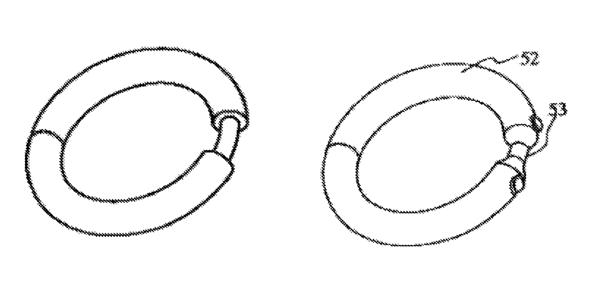
[0180]FIG. 15-1 to FIG. 15-3 show the transformer magnetic core used in the self-excitation push-pull converter of embodiment 3 of this invention, FIG. 15-1 is the front view of the transformer magnetic core used in embodiment 3 of this invention; FIG. 15-2 is the side view of the transformer magnetic core used in embodiment 3 of this invention; FIG. 15-3 is the top view of the transformer magnetic core used in embodiment 3 of this invention; and FIG. 15-4 is the 3D view of the transformer magnetic core used in embodiment 3 of this invention. There is also a small partial section 53 with a small area of the magnetic core, the main section 52, and the length of the partial section is very short. The working principle is identical to that in the above description of the invention and in embodiments 1 to 2, so it will not be repeated here.


PUM

PropertyMeasurementUnit
lengthaaaaaaaaaa
lengthaaaaaaaaaa
outer diameteraaaaaaaaaa

Abstract

A self-excitation push-pull type converter with a transformer having a closed magnetic core or iron core, which formed of a main part (52) and a local part (53). The local part reaches magnetic saturation earlier than the main part under the same increasing magnetic field excitation. When the self-excitation push-pull type converter is in a light load state, the efficiency is significantly improved, and further improved in a rated load state. As the number of turns of the coil on the magnetic saturation transformer is reduced, the working frequency of the converter increases while still keeping the loss low. The probability of generating a current peak at the moments of switching on or off is reduced, thereby further improving the efficiency and reducing output ripples.

Description

CROSS-REFERENCE TO RELATED APPLICATIONS[0001]This application claims priority from CN Application No. 201110436259.7, filed Dec. 22, 2011 and PCT Application No. PCT / CN2012 / 073867, filed Apr. 12, 2012, the contents of which are incorporated herein in the entirety by reference.FIELD OF THE INVENTION[0002]This invention is related to switching power, especially switching power of self-excitation push-pull type converter.BACKGROUND OF THE INVENTION[0003]In the existing self-excitation push-pull type converters, their circuit structure is based on the DC converter of self-excitation push-pull transistor single transformer invented by G. H. Royer in the United States in 1955, it is also referred to as Royer circuit, which is the start to realize high frequency conversion control circuit; some circuits are based on the self-excitation push-pull dual transformer circuit of Jensen of the United States in 1957, which was later known as self-oscillating Jensen circuit or Jensen circuit; both ...

Claims


Application Information

Patent Timeline
Patent Type & Authority Patents(United States)
IPC IPC(8): H02M7/538H02M3/338H01F3/14H01F30/16
CPCH02M7/538H02M3/3384H01F3/14H01F30/16
Inventor WANG, BAOJUN
Owner MORNSUN GUANGZHOU SCI & TECH
Why Eureka
Try Eureka