
Infiltration device and method

a technology of infiltration device and infiltration layer, which is applied in the direction of lighting and heating apparatus, charge manipulation, furnaces, etc., can solve the problems of serious affecting the consistency of the product performance, the infiltration process is highly sensitive to temperature, and the ordinary high temperature vacuum furnace cannot meet the requirements, so as to improve the consistency of the infiltration layer of magnets, eliminate the difference in the temperature of magnets, and improve the effect of infiltration process

Active Publication Date: 2018-11-27
BAOTOU TIANHE MAGNETICS TECH CO LTD
View PDF7 Cites 0 Cited by
  • Summary
  • Abstract
  • Description
  • Claims
  • Application Information

AI Technical Summary

Benefits of technology

[0019]a vent opening / closing unit provided below the vents for opening / closing the vents, the vent opening / closing unit having a reflective screen that serves to keep the temperature when the vent opening / closing unit is in a closed state, wherein the vents are not completely closed when the vent opening / closing unit is in the closed state.
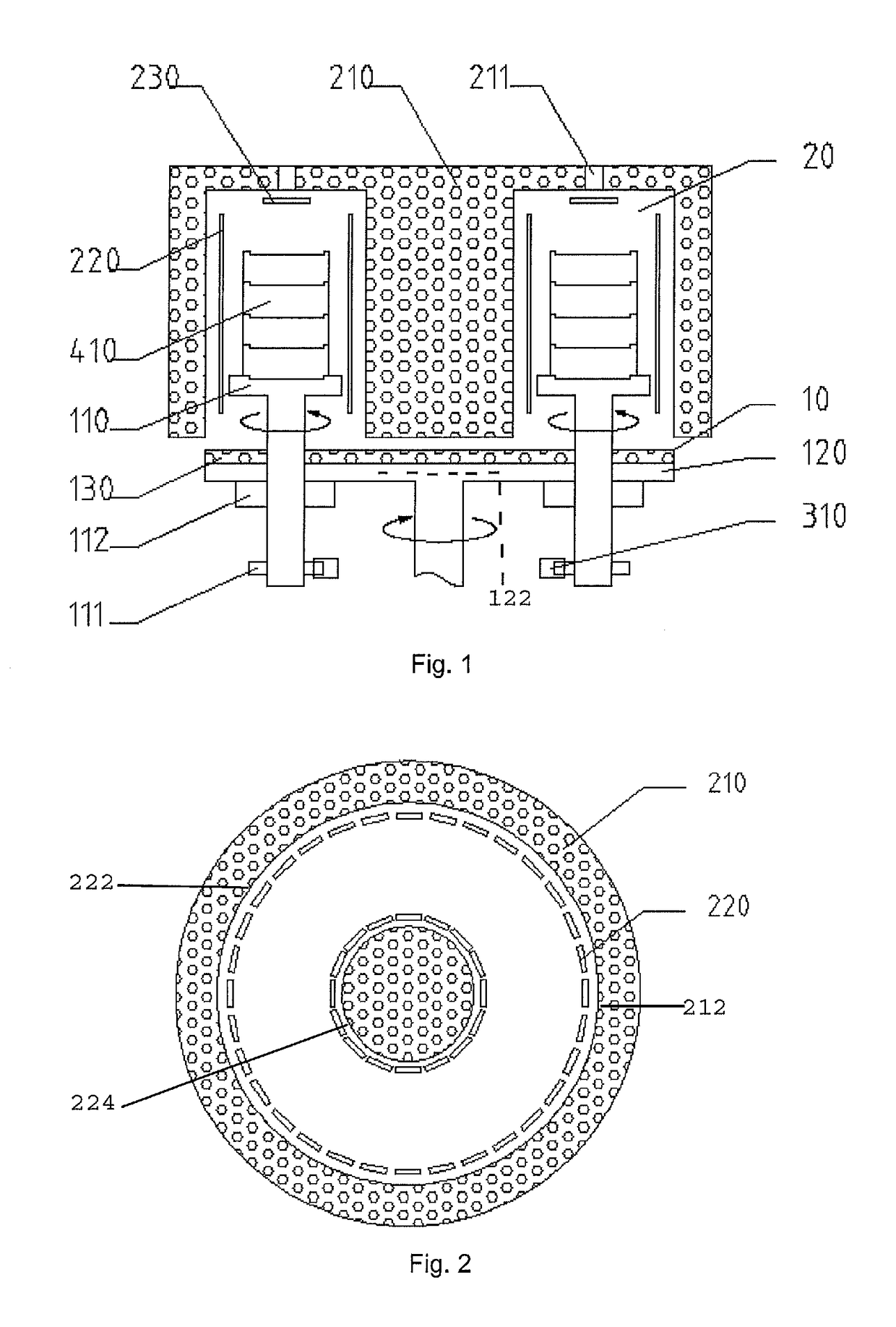
[0044]The invention brings about the following advantageous technical effects. The material box is placed on the rotary bracket, spins along with the rotary bracket and revolves around the annular groove of the heating room, thus achieving high temperature infiltration by rotary transposition and ensuring equality of the condition on the position of magnets. The material boxes are concentrically placed on the rotary bracket, thereby further ensuring equality of the condition on the position of magnets. Furthermore, the heating room has an annular groove structure and performs equal-distance heating from both sides, thereby realizing equality of the condition on the heating environment. Therefore, the invention eliminates a difference in the temperature of magnets caused by the temperature difference at different positions of the heating room, and improves consistency of the thickness of infiltration layers of magnets; the consistency of the performance of finished products is also improved; moreover, when the speed of increasing temperature or decreasing temperature is raised, the consistency of the temperature of magnets can be also ensured, thus reducing energy consumption and shortening production cycle.

Problems solved by technology

However, the infiltration process is highly sensitive to the temperature, and an ordinary high temperature vacuum furnace cannot meet the requirements.
The difference in the heating temperature for magnets at different positions and the difference in the speed of increasing temperature or decreasing temperature will both lead to differences in the thickness and quality of infiltration layers of the magnets, thus seriously affecting the consistency of the performance of the products, and even interrupting normal production.
When an ordinary vacuum heat treatment furnace is used to perform surface layer infiltration, the effect is not desirable.
As a result, the finished products are inconsistent in the depth of the infiltration layer, and their performance differs from one to another.

Method used


Image

  • Infiltration device and method
  • Infiltration device and method
  • Infiltration device and method

Examples


embodiment 1

[0075]As shown in FIG. 1, the infiltration device comprises a rotary tray 10, rotary brackets 110, heating rooms 20 and material boxes 410, etc.

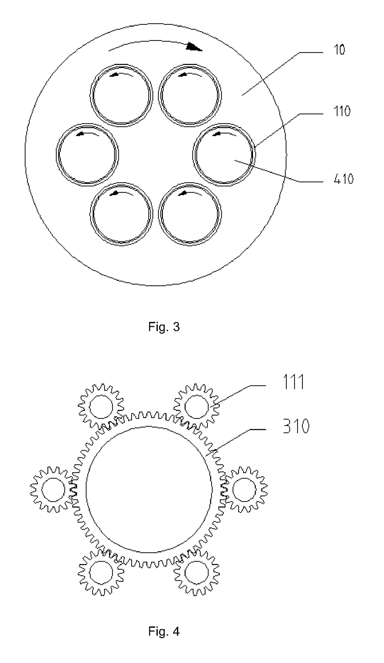
[0076]The rotary brackets 110 are installed on the rotary tray 10 located below the rotary brackets 110, and a plurality of rotary brackets are installed on the rotary tray 10 in an annular array so as to perform high temperature infiltration on a plurality of material boxes. The rotary brackets 110 are made from thermal resistant steel. The rotary brackets 110 and the rotary tray 10 form one piece via rotary mechanisms 112. The rotary tray 10 is provided with holes, in which bearings are installed. The rotary brackets 110 are installed on the rotary tray via the bearings.

[0077]With reference to FIGS. 1 and 4, a first transmission member for driving the rotary tray 10 to rotate in installed below the rotary tray 10. A second transmission member is installed below the rotary bracket 110 so as to drive the rotary bracket to spin via the rotati...

embodiment 2

[0083]Taking a sintered NdFeB magnet infiltrated with Dysprosium Fluoride and coated with super fine Dysprosium Fluoride powder all over the surface as an example, a workflow of the infiltration method according to the invention will be described in detail hereinafter with reference to the drawings. Of course, those skilled in the art can also use the infiltration method of the invention to perform relevant high temperature infiltration operations on other magnets.

[0084]In this embodiment, the specific process is as follows:

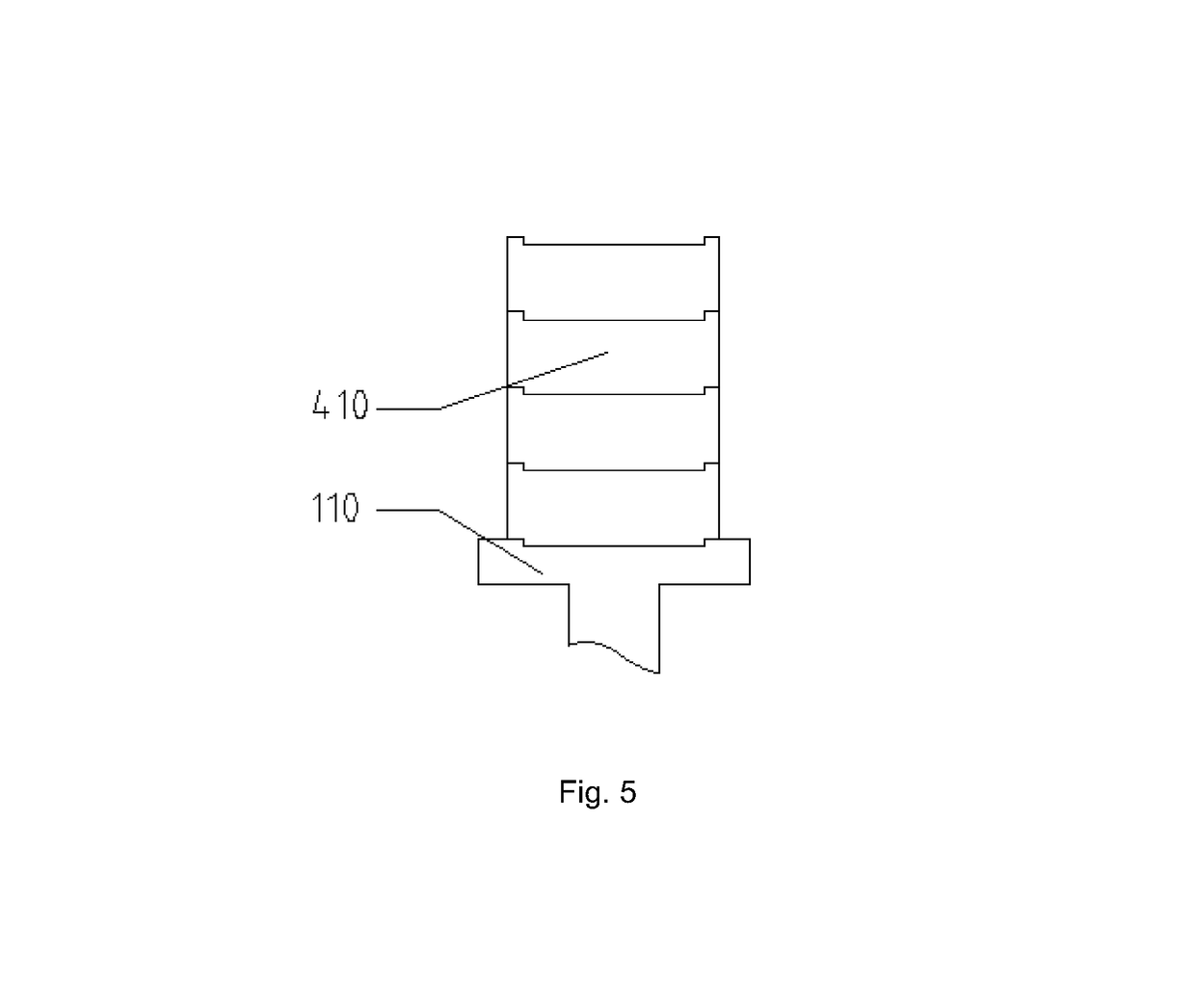
[0085]Charging stage: an annular array of sintered NdFeB magnets coated with super fine Dysprosium Fluoride powders all over the surface is loaded in the cylindrical material box 410, wherein the magnets can be placed in a single layer or in several layers in the material box 410. The elevating mechanism lowers the rotary tray 10 and the rotary brackets 110 as a whole, wherein the elevating mechanism can be powered by a hydraulic cylinder. The material boxes 410 ...


PUM

PropertyMeasurementUnit
thicknessaaaaaaaaaa
thicknessaaaaaaaaaa
widthaaaaaaaaaa

Abstract

An infiltration device comprises a heating room, a rotary tray, a rotary bracket, a material box, an elevating mechanism and a transmission device, wherein the heating room has an annular groove, and the rotary tray is arranged below an opening end at a lower end of the heating room; the rotary bracket is installed on the rotary tray; the material box is arranged on the rotary bracket; the rotary tray and the material box can move upward and downward under the action of the elevating mechanism; the rotary bracket can spin in the annular groove and revolve around a central axis of the rotary tray under the action of the transmission device. The infiltration method provided by the invention comprises the steps of charging, vacuum-pumping, high temperature infiltrating, cooling, discharging, etc.

Description

CROSS-REFERENCE TO RELATED APPLICATIONS[0001]The present application claims priority from Chinese Patent Application No. 201510514589.1 filed Aug. 20, 2015, the disclosure of which is hereby incorporated herein by reference.TECHNICAL FIELD OF THE INVENTION[0002]The invention relates to an infiltration device and method, and in particular, to an infiltration device and method for infiltration treatment of surface layers of magnets.BACKGROUND OF THE INVENTION[0003]Surface infiltration of Dysprosium and Terbium is a new technology for surface layer treatment after a high performance NdFeB rare earth permanent magnet is sintered into a blank. Through infiltration of Dysprosium and Terbium into a certain depth range from the surface layer of the magnet, the thermal resistance and coercive force of the magnet can be prominently improved. Therefore, such an infiltration technology has been preliminarily applied in the field of manufacturing a high performance NdFeB rare earth permanent mag...

Claims


Application Information

Patent Timeline
Patent Type & Authority Patents(United States)
IPC IPC(8): C23C14/04H01F41/02F27D3/00F27D7/02F27D19/00F27D21/00
CPCC23C14/046F27D3/0024F27D7/02F27D21/00H01F41/0293F27D19/00F27D2003/0034
Inventor MIAO, JUCHANGZHAI, YONGMA, JIANXINGAO, ENFENGSONG, YANLINGDIAO, SHULINDONG, YIYI, HAIBOWU, SHUJIEYUAN, YICHEN, YAYUAN, WENJIE
Owner BAOTOU TIANHE MAGNETICS TECH CO LTD
Learn More