
Clock duty cycle correction circuit

a duty cycle and correction circuit technology, applied in pulse generators, pulse manipulation, pulse techniques, etc., can solve the problems of data loss during data sampling, common errors in the first and second differential clock signals, and duty cycle errors, so as to prevent jitter, improve accuracy, and facilitate manufactur

Active Publication Date: 2019-02-12
SYNOPSYS INC +1
View PDF33 Cites 6 Cited by
  • Summary
  • Abstract
  • Description
  • Claims
  • Application Information

AI Technical Summary

Benefits of technology

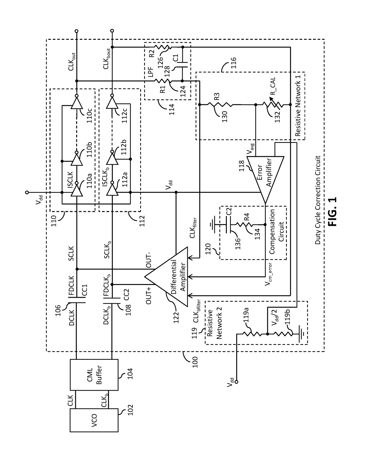
The duty cycle correction circuit is designed to be easy to make and has a simple design. It helps to prevent errors in the first and second clock signals, which can cause jitter.

Problems solved by technology

Due to changes in physical conditions such as temperature, aging of the VCO, voltage fluctuation, electromagnetic noise, and the like, the duty cycles corresponding to the first and second differential clock signals may deviate from 50%, thereby causing errors in the duty cycles.
The common errors in the first and second differential clock signals are caused when the duty cycles of the first and second differential clock signals deviate equally from 50%.
The differential and common errors in the first and second differential clock signals may lead to jitter therein.
Jitter may lead to data loss during data sampling.
However, inclusion of the charge pump in such DCC circuits leads to a complex circuit design thereof.
Further, the power consumed by the DCC circuits is high.
However, the DCC circuits employing the differential amplifiers fail to rectify the common errors in the first and second differential clock signals, thereby inducing jitter in the first and second differential clock signals.

Method used


Image

  • Clock duty cycle correction circuit
  • Clock duty cycle correction circuit

Examples


Embodiment Construction

[0016]As used in the specification and claims, the singular forms “a”, “an” and “the” include plural references unless the context clearly dictates otherwise. For example, the term “an article” may include a plurality of articles unless the context clearly dictates otherwise.

[0017]Those with ordinary skill in the art will appreciate that the elements in the figures are illustrated for simplicity and clarity and are not necessarily drawn to scale. For example, the dimensions of some of the elements in the figures may be exaggerated, relative to other elements, in order to improve the understanding of the present invention.

[0018]There may be additional components described in the foregoing application that are not depicted on one of the described drawings. In the event such a component is described, but not depicted in a drawing, the absence of such a drawing should not be considered as an omission of such design from the specification.

[0019]Before describing the present invention in ...


PUM


Abstract

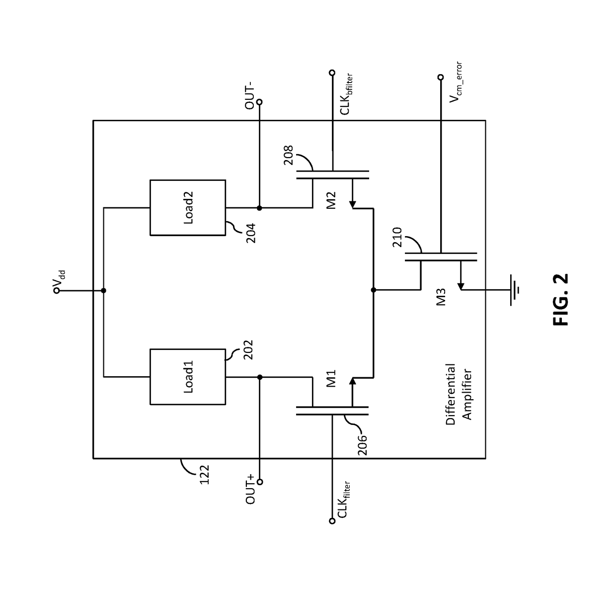
A duty cycle correction (DCC) circuit includes first and second pluralities of logic gates, a low pass filter, an error amplifier, and a differential amplifier. The DCC circuit receives first and second clock signals from the VCO. The first and second pluralities of logic gates receive first and second superimposed clock signals and generate first and second output clock signals, respectively. The error amplifier rectifies a common error of the first and second output clock signals, and generates a common mode error voltage signal. The differential amplifier generates first and second error signals based on the common mode error voltage signal. The first and second error signals converge the duty cycles of the first and second output clock signals to a 50% duty cycle.

Description

CROSS-RELATED APPLICATIONS[0001]This application claims priority of Indian Application Serial No. 201741034036, filed Sep. 25, 2017, the contents of which are incorporated herein by reference.FIELD OF THE INVENTION[0002]The present invention relates generally to the field of integrated circuits, and, more particularly, to a duty cycle correction circuit.BACKGROUND[0003]Digital circuits, and, more particularly, synchronous digital circuits employ a periodically oscillating signal, i.e., a clock signal for coordinating various functions performed by the synchronous digital circuits. Such functions typically include sampling data that is transmitted within and outside the synchronous digital circuits. The clock signal may be generated by crystal oscillators, voltage controlled oscillators (VCOs), astable multivibrators, and the like. A duty cycle of the clock signal is defined as a ratio of an ON time period of the clock signal to a total time period of the clock signal. For example, w...

Claims


Application Information

Patent Timeline
Patent Type & Authority Patents(United States)
IPC IPC(8): H03K3/017H03K7/08H03F3/45H03K5/04
CPCH03F3/45179H03K7/08H03K5/1565H03F3/45183
Inventor KANSAL, SHOURYACHATTOPADHYAY, BIMANMEHTA, RAVIWADEKAR, JAYESH
Owner SYNOPSYS INC
Learn More