
System comprising duel-fuel and after treatment for heavy-heavy duty diesel (HHDD) engines

Active Publication Date: 2019-05-14
CLEAN POWER TECH LLC
View PDF9 Cites 104 Cited by
  • Summary
  • Abstract
  • Description
  • Claims
  • Application Information

AI Technical Summary

Benefits of technology

The present invention is a system for reducing emissions in pre-2010 and 2010 engines. It includes an after-treatment system with a combination of a selective catalytic reduction (SCR) system, a diesel particulate filter (DPF), and an exhaust thermal management system (ETMS). The system also includes a dual fuel system that reduces diesel fuel consumption and carbon dioxide (CO2) emissions. The ETMS helps to quickly heat up the engine system during cold starts and also helps to achieve rapid activation of the SCR system. The system can be controlled using multiple sensors and controllers, and it can be used in both new and pre-existing engines. Overall, the system helps to achieve low levels of emissions in accordance with current regulations.

Problems solved by technology

Because these configurations utilize “high-pressure” direct NG and diesel fuel injector systems, they are very costly and have had a history of poor reliability.
These configurations have modest cost but lack the NG metering precision needed to attain compliance with U.S. EPA and CARB regulated exhaust emission standards.
These systems can be expensive and rely fully on digital information from their mixed-fuel ECM.
If the engine system was to suffer an unexpected event, (i.e., accident resulting in a loss of post turbo induction system integrity), the NG injected system may keep injecting NG fuel creating a potentially hazardous situation.
Further, their operation can reduce the engine's durability due to the change in combustion dynamics and associated higher temperatures if these systems are allowed to “over-fuel”.

Method used


Image

  • System comprising duel-fuel and after treatment for heavy-heavy duty diesel (HHDD) engines
  • System comprising duel-fuel and after treatment for heavy-heavy duty diesel (HHDD) engines
  • System comprising duel-fuel and after treatment for heavy-heavy duty diesel (HHDD) engines

Examples


Embodiment Construction

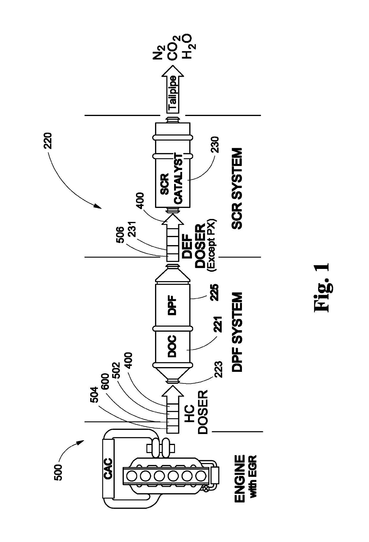
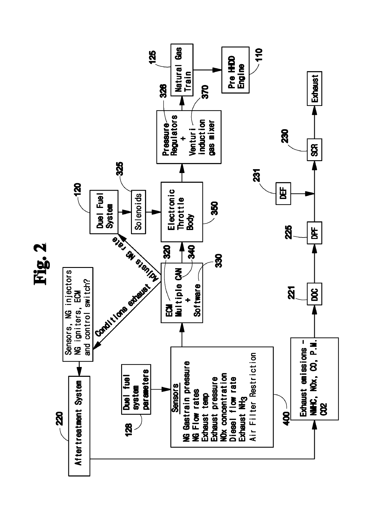
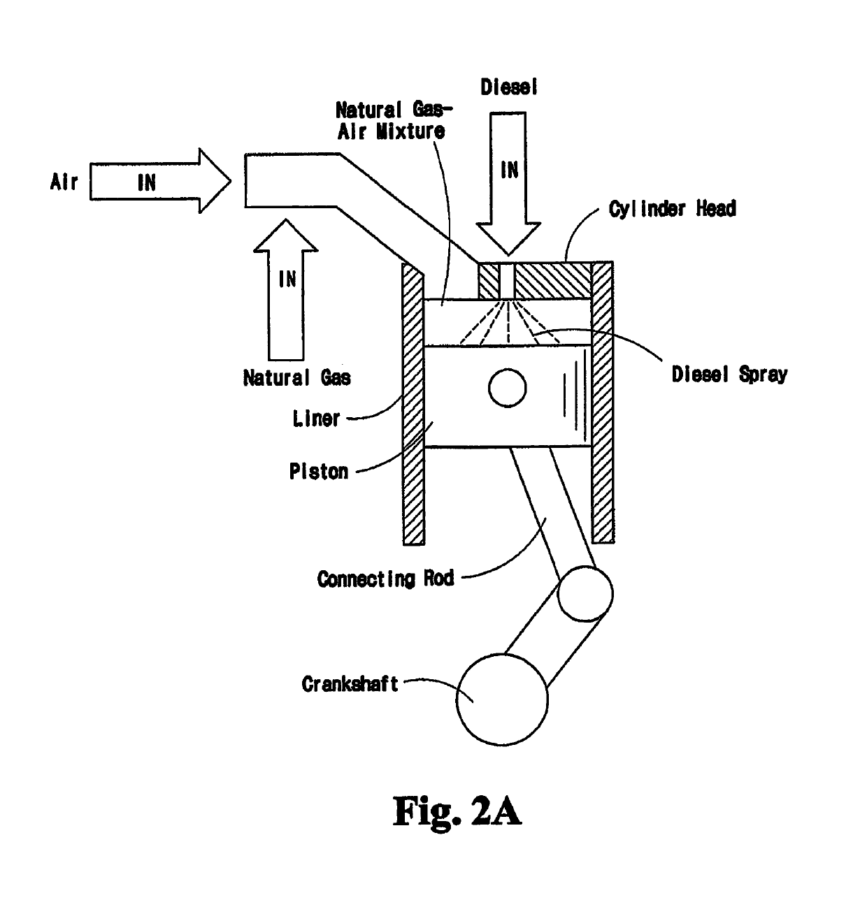
[0032]In the embodiment employed with 2010 and newer HHDD engines, the APG V6000 (or V6000) 1 (FIG. 2) of the present invention in its simplest embodiment is combined with a 2010 or newer Heavy-Heavy Duty Diesel (HHDD) engine 110 and comprises and APG Dual Fuel system 120 substituting an amount of natural gas (NG) 25 for diesel fuel 130 (see FIGS. 2, 2a and 2b.) and an exhaust thermal management system 500 comprising means to rapidly heat the factory-provided DOC / DPF and SCR systems.

[0033]For pre-2010 HHDD engines the APG V6000 is combined with a pre-2010 Heavy-Heavy Duty Diesel (HHDD) engine 110 and comprises an APG Dual-Fuel system 120 for substituting an amount of natural gas (NG) 25 for diesel fuel 130 (see FIGS. 2, 2a and 2b.). The APG V6000 1 comprises, a “full” after-treatment system 220, and at least one Electronic Control Module(s) (ECM's) 320, with appropriate software 330, utilizing multiple Communication Area Network (CAN) channels to precisely control NG 25 fuel substit...


PUM


Abstract

The present invention provides up-fit after treatment technology for bringing Heavy-Heavy Duty Diesel (HHDD) engine powered vehicles into compliance with the Title 13 CCR, Part 2025 mandate (meeting 2010 criteria emission standards). It also includes a Dual Fuel system, Exhaust Thermal Management System further reducing: NOx constituents, consumption of diesel fuel, particulate matter and CO2 emissions. The invention further comprises multiple sensors that provide data to electronic control module(s). The APGV6000 enables rapid after-treatment thermal activation, compares “real-time” sensor data with target data, and adjusts the after treatment system and / or dual fuel system and / or Exhaust Thermal Management system to produce exhaust emissions well below 2010 exhaust emission standards. For 2010 and newer HHDD engine applications, the V6000 comprises the Dual Fuel and exhaust thermal management system to affect rapid after-treatment activation, reduced NOx emissions well below, 2010 (current) standards, reduce diesel fuel usage and reduce CO2 emission.

Description

CROSS REFERENCE TO PRIOR APPLICATIONS[0001]This application claims benefit from United States Patent and Trademark Office Provisional Application No. 62 / 387,352 which was filed on Dec. 23, 2015.FIELD OF THE INVENTION[0002]Over the past four decades, various U.S. EPA and California Air Resource Board (CARE) regulations, mandates and laws have been enacted with the goal of reducing smog forming, health challenging vehicular exhaust emissions, and reduce the use of fossil fuels. Many of these regulations address exhaust emissions from over-the-road trucks powered by heavy duty diesel engines.[0003]The present invention provides an emissions management system (tradename APG V6000 (“V6000”)) comprising a dual fuel system, appropriate after treatment technology and exhaust thermal management system.[0004]The APG V6000 pre-2010 configuration provides means by which pre-2010 Heavy Heavy Duty Diesel (HHDD) engine powered vehicles may be brought into compliance with the Title 13 CCR, Section ...

Claims


Application Information

Patent Timeline
IPC IPC(8): F01N3/10F01N13/00F01N3/20F01N11/00F02B43/04F02D19/08F02D19/06F02M21/02F01N3/027F02B43/10
CPCF01N3/204F02B43/10F02D19/0602F02D19/081F02D19/0647F01N3/2006F02B43/04F01N3/2066F01N3/103F01N11/007F02M21/0215F01N11/002F01N13/008F01N3/0275F02B2043/103F01N2550/02F01N2590/02Y02A50/20Y02T10/12Y02T10/30Y02T10/40
Inventor SCHILTZ, MIKE
Owner CLEAN POWER TECH LLC
Learn More