
Electrofluidic support plates and preparation method therefor, and electrofluidic apparatus

a technology of electrofluidic apparatus and support plate, which is applied in the direction of fluid controllers, identification means, instruments, etc., can solve the problems of ink (oil) incomplete return problem, damage to hydrophobic layer, and inability to completely return ink, so as to improve the switching on-off performance of the device and improve the quality and reliability of the produ

Active Publication Date: 2019-06-04
SOUTH CHINA NORMAL UNIVERSITY +2
View PDF4 Cites 0 Cited by
  • Summary
  • Abstract
  • Description
  • Claims
  • Application Information

AI Technical Summary

Benefits of technology

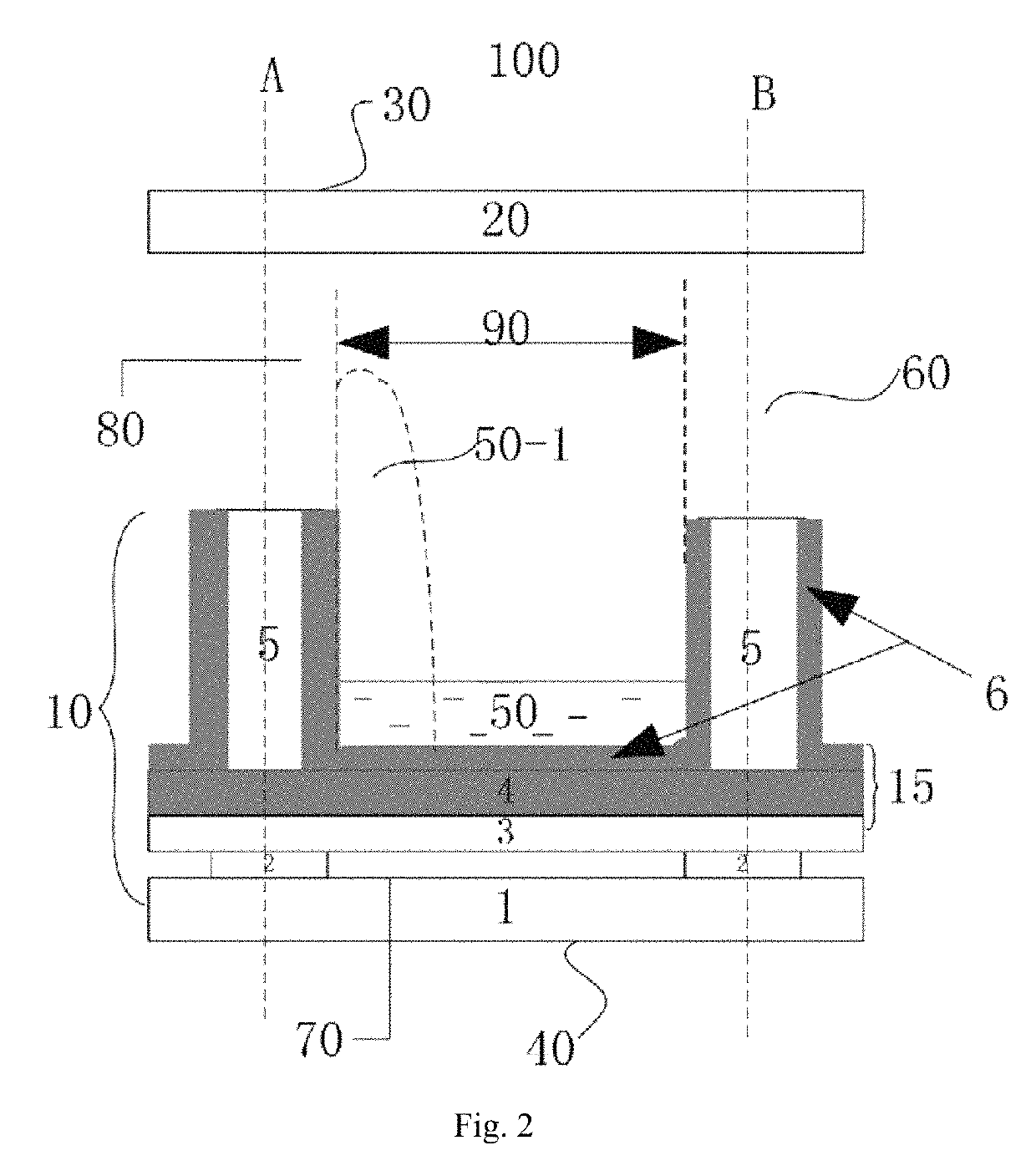
This approach prevents physical and chemical damage to the hydrophobic layer, ensuring complete ink return and enhancing the reliability and switching performance of electrofluidic devices by eliminating gaps between the hydrophobic layer and pixel walls.

Problems solved by technology

However, during the plasma etching or heat treatment, the hydrophobic layer will inevitably be damaged and the hydrophobic and insulating properties will be affected.
This will cause the ink (oil) incompletely return problem when the voltage is turned off.
Therefore, the quality of the display device manufactured by the method is unsatisfactory.
However, there is a problem with this method.
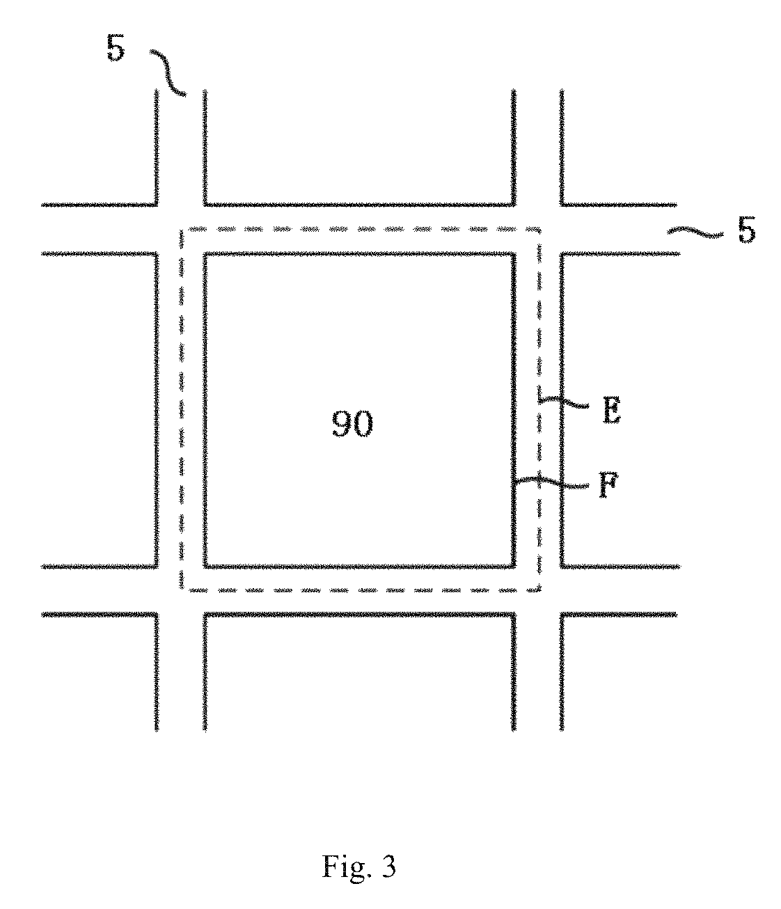
After the hydrophobic material being etched into a grid-like pattern, a short-circuit problem will be caused by the water on the hydrophobic insulated layer (or ionic liquid or a salt solution such as an aqueous solution of sodium chloride) contacting a lower electrode after switching on and off many times due to a gap between the hydrophobic layer and the walls material while bonding, thereby affecting the reliability of the device.

Method used


Image

  • Electrofluidic support plates and preparation method therefor, and electrofluidic apparatus
  • Electrofluidic support plates and preparation method therefor, and electrofluidic apparatus
  • Electrofluidic support plates and preparation method therefor, and electrofluidic apparatus

Examples


Embodiment Construction

[0030]It should be noted that the embodiments in the application and the features in the embodiment can be mutually combined in case of no conflicts.

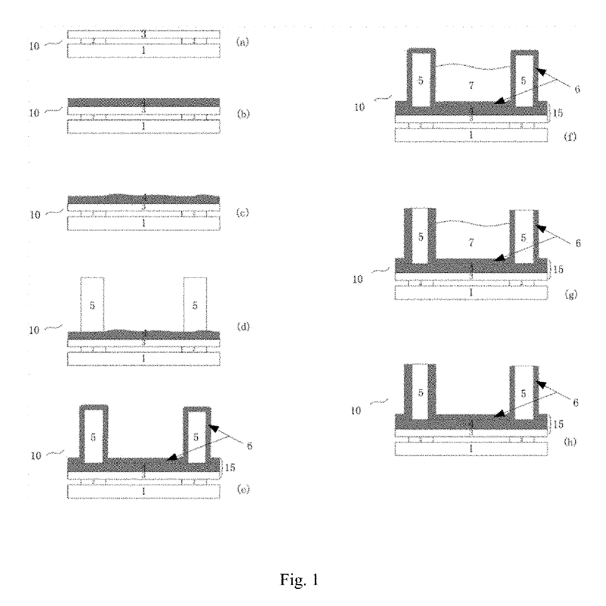
[0031]As shown in FIG. 1, according to an exemplary embodiment of the present disclosure, an electrofluidic support plate 10 of the present disclosure is prepared by the following steps.

[0032]1) As shown in FIG. 1 (a), providing a substrate 1, which has a surface provided with an electrode layer 2.

[0033]The substrate 1 may be a glass or polymer substrate, and also may be rigid or flexible. Generally, the electrode layer 2 is arranged on the substrate 1. In order to avoid short circuit between an upper substrate and a lower substrate, a dielectric layer 3 may be arranged on the electrode layer 2, and the dielectric layer 3 may be a layer of silicon oxide or a silicon nitride, and has a thickness of 200 nm for instance. Of course, the dielectric layer may also not be arranged, and the specific reasons shall be described in the following s...


PUM

PropertyMeasurementUnit
thicknessaaaaaaaaaa
thicknessaaaaaaaaaa
thicknessaaaaaaaaaa

Abstract

Disclosed is an electrofluidic support plate and a method for preparing the same, and an electrofluidic device comprising the support plate. The method comprises the following steps of: providing a substrate which has a surface provided with an electrode layer; arranging a first amorphous fluoropolymer layer on the surface of the substrate, and carrying out hydrophilic modification on a surface of the amorphous fluoropolymer layer; arranging pixel walls on the amorphous fluoropolymer layer after hydrophilic modification; arranging a second amorphous fluoropolymer layer which is a hydrophobic layer; the second amorphous fluoropolymer layer covering all surfaces of the pixel walls and a groove area encircled by the pixel walls; filling the groove area encircled by the pixel walls with a protective material; removing the second amorphous fluoropolymer layer not covered by the protective material and on a top of the pixel walls; and removing the protective material.

Description

CROSS REFERENCE TO RELATED APPLICATIONS[0001]This application is a 371 National Stage of International Application No. PCT / CN2016 / 070365, filed Jan. 7, 2016, now Publication No. WO 2017 / 028484, published Feb. 23, 2017, which claims priority benefit of Chinese Application No. 201510501123.8, filed Aug. 14, 2015, each of which is hereby incorporated by reference into this application.FIELD OF THE INVENTION[0002]The present disclosure relates to an electrowetting technology, and particularly to an electrofluidic support plate and a method for preparing the same, and an electrofluidic device comprising the support plate.BACKGROUND OF THE INVENTION[0003]Electrofluid is also known as electrowetting. At current, the electrofluidic display (EFD) technology has been widely used, and it provides an electrofluid-based display unit.[0004]For example, an electrofluidic device described in International Patent Application WO 2003 / 071346 comprises two support plates. A walls pattern (i.e., pixel w...

Claims


Application Information

Patent Timeline
Patent Type & Authority Patents(United States)
IPC IPC(8): G09F9/37G09G3/34G02B26/00G02F1/167
CPCG02F1/167G02B26/005G09G3/348G09F9/372G02B26/004B01L2400/0427
Inventor ZHOU, GUOFUWULI, FAHONGHAYES, ROBERT ANDREW
Owner SOUTH CHINA NORMAL UNIVERSITY
Learn More