
Dynamic range improvement for isotope ratio mass spectrometry

a mass spectrometry and dynamic range technology, applied in the field of mass spectrometers, controllers of mass spectrometers and methods of mass spectrometry, can solve the problems of limiting the flexibility of the detector array to allow, and additional scattered background, so as to reduce the overall scattered background significantly.

Active Publication Date: 2019-06-04
THERMO FISHER SCI BREMEN
View PDF11 Cites 0 Cited by
  • Summary
  • Abstract
  • Description
  • Claims
  • Application Information

AI Technical Summary

Benefits of technology

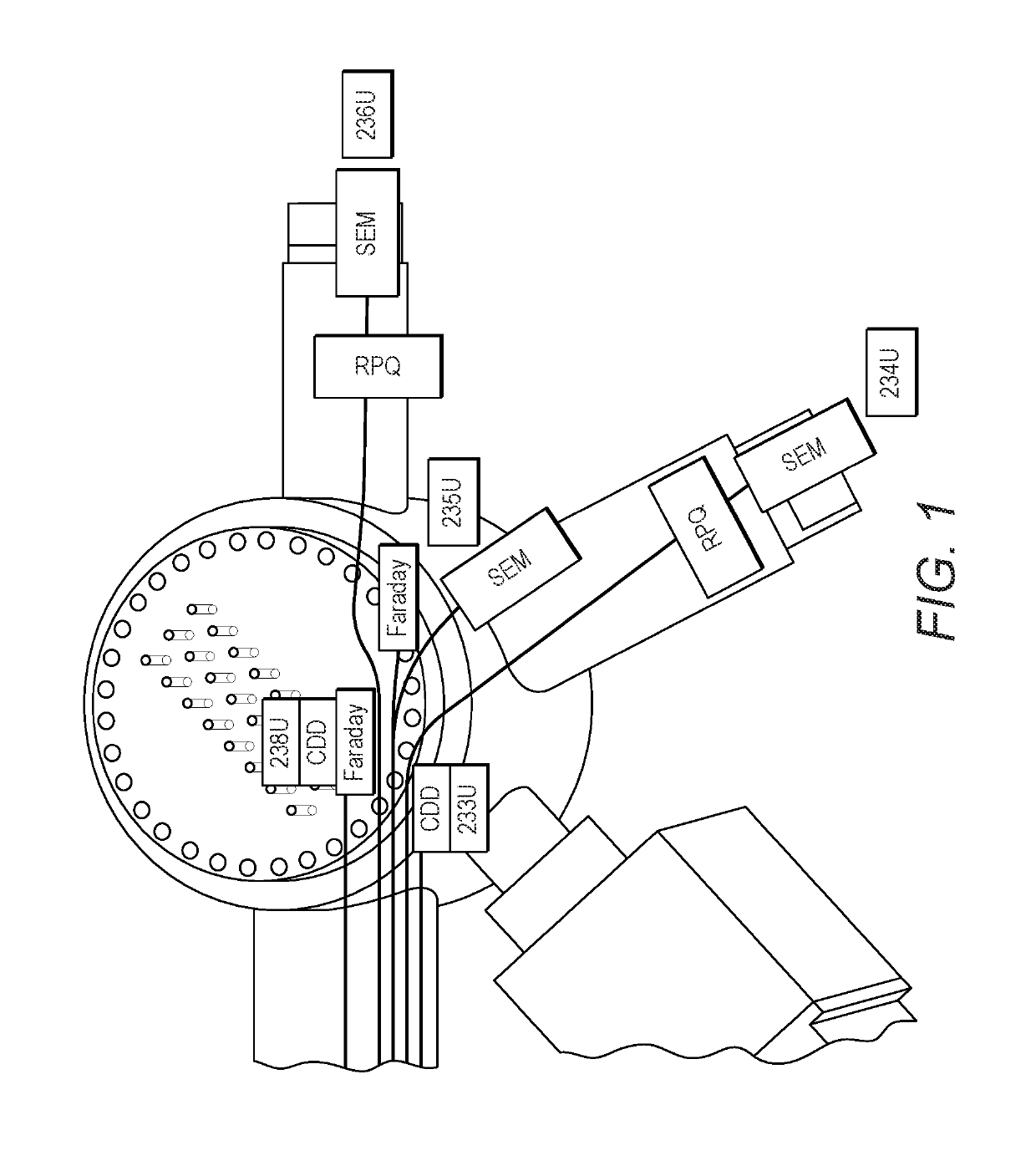
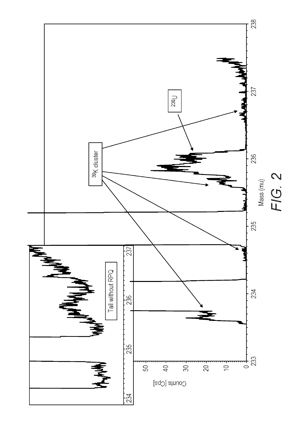
The invention proposes a method to measure the background during analysis using one or more additional detectors. This allows for online control of metastable production and interference control, while maintaining flexibility and speed of the instrument. The background measurement is made at the same time as the main beam is being detected, so there is no loss of throughput. The method also involves the use of protection plates to shield the main beam detectors from scattered background ions. The technical effect of the invention is to provide a more efficient and accurate way to measure the background during analysis.

Problems solved by technology

In particular, it allows precise scattered background control to be managed by standard Faraday collectors or other standard detectors (such as CDD an ion counting channel using a secondary electron multiplier or a photomultiplier as the amplification device), rather than very specific and bulky detector configurations (such as the use of energy filters or split flight tubes) that can also limit the flexibility of the detector array to allow for high precision isotope ratio measurements of other elements on the same instrument.
Another complication with known off-peak baseline control is that the baseline is measured in a condition which is not the measurement condition for the main beam.
As such, these beams may cause additional scattered background, which is different from the background during the real on-peak measurement when most ion beams are captured inside the detector.

Method used


Image

  • Dynamic range improvement for isotope ratio mass spectrometry
  • Dynamic range improvement for isotope ratio mass spectrometry
  • Dynamic range improvement for isotope ratio mass spectrometry

Examples


Embodiment Construction

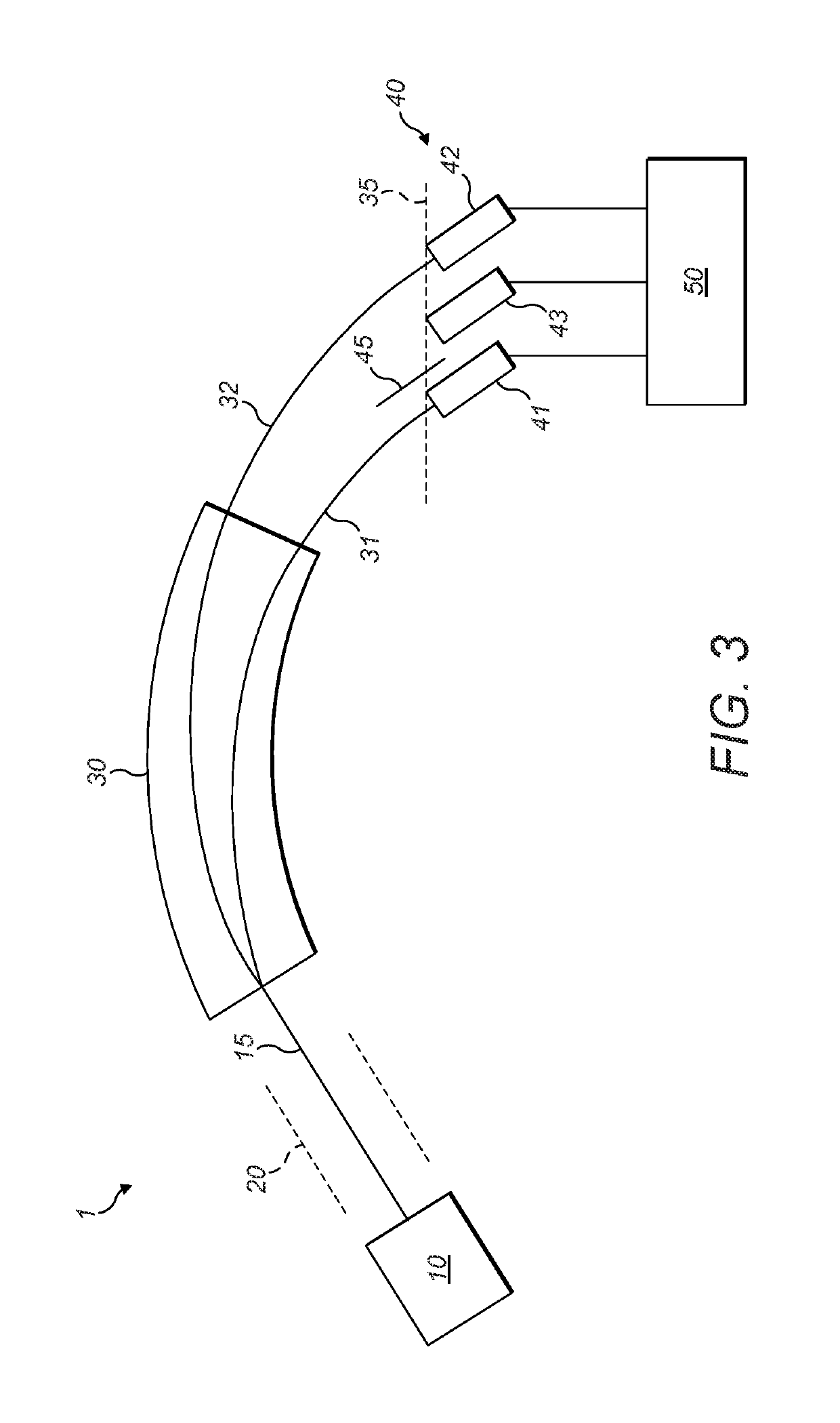
[0026]As noted above, it is proposed to use an additional detector or several additional detectors to measure the background during the analysis. Referring first to FIG. 2, there is shown a schematic illustration of a mass spectrometer 1. The mass spectrometer 1 comprises: an ion source 10; ion optics 20; a mass-to-charge dispersive element 30; an ion detection arrangement 40; and a processor 50. The ion optics 20 may comprise one or more optics selected from: an ion lens, an ion guide and a collision cell. The mass-to-charge dispersive element 30 is a magnetic sector in this embodiment. The ion detection arrangement 40 is in the form of a collector array and comprises: a first main beam detector 41; a second main beam detector 42; a background level detector 43; and a shielding plate 45. The first 41 and second 42 main beam detectors and the background level detector 43 are positioned at the focal plane 35 of the magnetic sector 30.

[0027]The ion source 10 generates an ion beam 15, ...


PUM

PropertyMeasurementUnit
thickaaaaaaaaaa
sizeaaaaaaaaaa
sizeaaaaaaaaaa

Abstract

In a mass spectrometer, a mass-to-charge dispersive element separates received ions spatially according to their mass-to-charge ratios, to provide a dispersed ion beam thereby. An ion detection arrangement that detects the dispersed ion beam comprises: at least one primary ion detector, each detecting spatially separated ions having mass-to-charge ratios within a respective desired range and each providing a respective main beam signal based on its respective detected ions; and at least one secondary ion detector, each detecting ions having mass-to-charge ratios outside all of the desired ranges simultaneously with the at least one primary ion detector detecting the spatially separated ions and each providing a respective background signal based on its respective detected ions. At least one mass intensity measurement is provided for the received ions having a mass-to-charge ratio within the desired range, based on the at least one main beam signal and the at least one background signal.

Description

CROSS-REFERENCE TO RELATED APPLICATION[0001]This application claims the priority benefit under 35 U.S.C. § 119 to British Patent Application No. 1514481.9, filed on Aug. 14, 2015, the disclosure of which is incorporated herein by reference.TECHNICAL FIELD OF THE INVENTION[0002]The invention relates to a mass spectrometer, a controller for a mass spectrometer and method of mass spectrometry, particularly in the field of isotope ratio mass spectrometry.BACKGROUND TO THE INVENTION[0003]Multi-collector mass spectrometers are well-known, particularly for distinguishing between isotopes. A mass-to-charge dispersive element, such as a magnetic sector, separates ions spatially according to their mass-to-charge ratios. Multi-collector measurements are the preferred method for high precision isotope ratio measurement, because the parallel detection of the isotopes or isotopologues may eliminate the effect of signal fluctuations on the precision of the measured isotope ratio. The detector arra...

Claims


Application Information

Patent Timeline
Patent Type & Authority Patents(United States)
IPC IPC(8): B01D59/44H01J49/00H01J49/02H01J49/30G01N27/62
CPCH01J49/30H01J49/025H01J49/0027B01D59/44G01N27/62H01J49/0036H01J49/009
Inventor RADKE, JENSHILKERT, ANDREASTRINQUIER, ANNESCHWIETERS, JOHANNES
Owner THERMO FISHER SCI BREMEN
Learn More