
Systems and methods for testing for a gas leak through a gas flow component

a technology of gas flow and detection system, which is applied in the direction of fluid/vacuum fluid tightness measurement, analysis by thermal excitation, material excitation, etc., can solve the problems of helium leak detection system high cost, helium suffers from shortage, and helium-based leak detection system can be expensiv

Active Publication Date: 2019-09-10
MECANIQUE ANALYTIQUE INC
View PDF33 Cites 2 Cited by
  • Summary
  • Abstract
  • Description
  • Claims
  • Application Information

AI Technical Summary

Benefits of technology

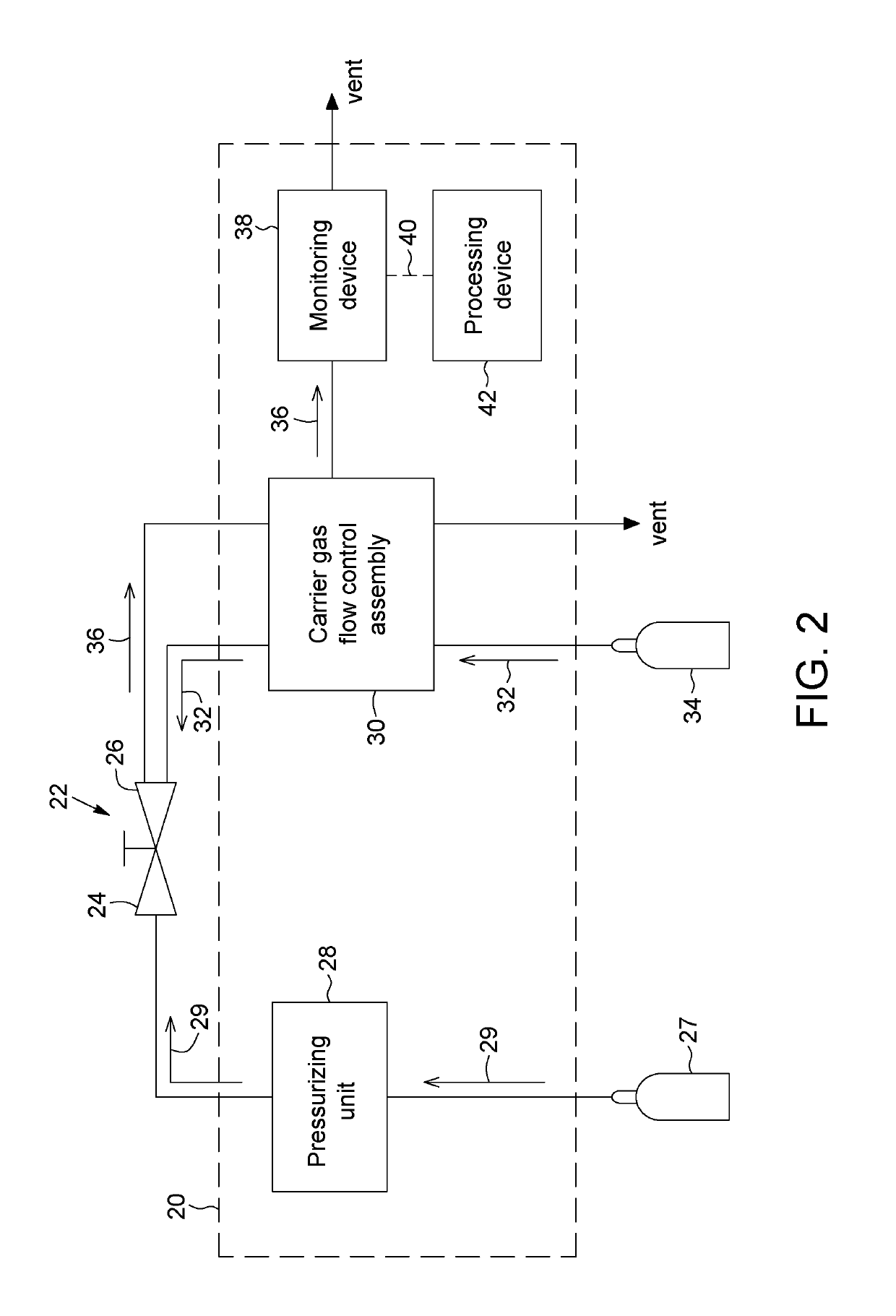
The present invention provides a system and method for testing for gas leaks in a gas flow component. The system includes a pressurizing unit, a carrier gas flow control assembly, and a monitoring device. The method involves exposing the gas flow component to a tracer gas, circulating the carrier gas through the outlet zone of the component, and monitoring the spectroscopic emission of the tracer gas. The system and method can detect gas leaks with high accuracy and efficiency, and can be used in a variety of applications such as industrial and manufacturing processes.

Problems solved by technology

Helium-based leak detection systems can however be expensive, as a complete mass spectrometer carries a high cost, in addition to a vacuum pump, vacuum hardware, etc.
Furthermore, helium suffers from a supply shortage and several attempts to replace helium in analytical systems have been documented.
Typically, orifice-type leaks can appear through the wall of a vessel or gas canister, tubing or fitting with inadequate sealing area, etc.
Gases of low molecular size, like hydrogen, flowing easily through the orifice channel may be unsafe to use for detecting this type of gas leak.
Capillary-type leaks can also appear through fittings, generally because they are not properly tightened or because the surface of the fitting wall is porous or scratched.
For example, permeation-type leaks can appear in valves under high pressure through plastic or polymer sealing device, like gaskets and O-rings.

Method used


Image

  • Systems and methods for testing for a gas leak through a gas flow component
  • Systems and methods for testing for a gas leak through a gas flow component
  • Systems and methods for testing for a gas leak through a gas flow component

Examples


Embodiment Construction

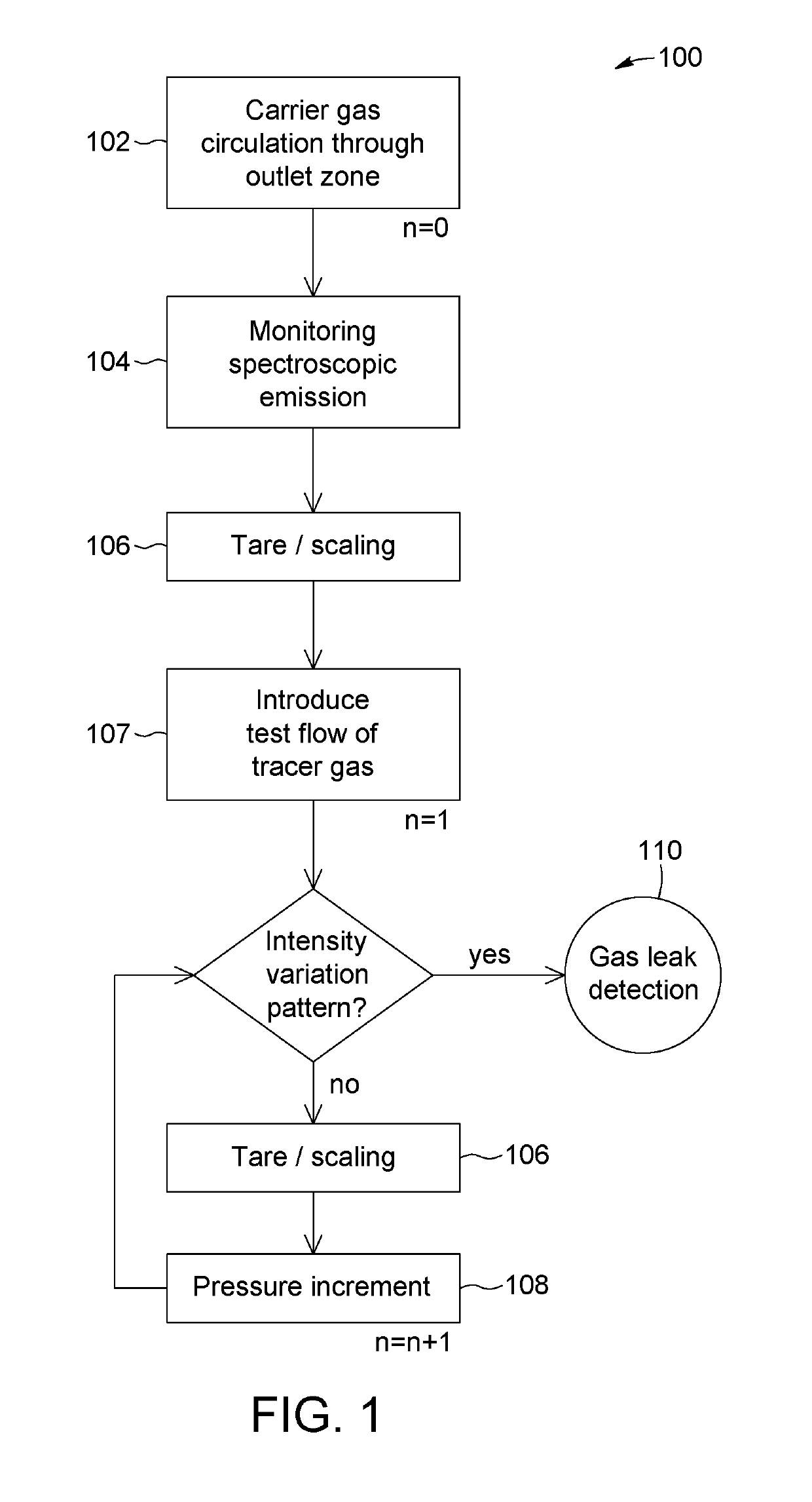
[0083]In accordance with aspects of the invention, there are provided methods and systems making use of spectroscopic emission techniques to detect various types of gas leaks from a gas flow component.

[0084]It will be readily understood that the gas flow component may be embodied by various devices through which analytical gases can circulate. In some implementations the gas flow component may be a valve, such as for example a diaphragm valve, rotary valve, needle valve, ball valve, etc. In other implementations the gas flow component may be a fitting, a vessel or the like. In additional implementations, the gas flow component may be a system or assembly composed of several elements, such as for example a sampling line. The gas flow component is assumed to allow a gas flow therethrough, and therefore includes an inlet zone through which gas is inserted and an outlet zone from which gas exits the gas flow component. It will be readily understood that the identification of the inlet a...


PUM


Abstract

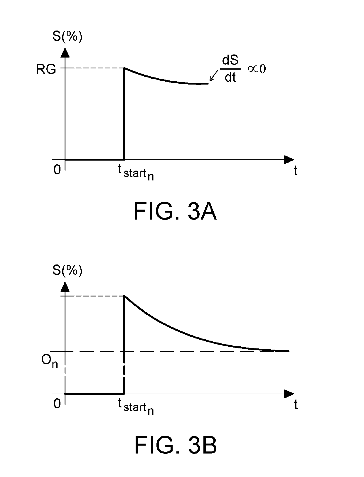
Methods and systems of testing for a gas leak between an inlet zone and an outlet zone of a gas flow component in a shut state are provided. Different tracer and carrier gases are used. The carrier gas is circulated through the outlet zone of the gas flow component to purge the tracer gas from this outlet zone. A spectroscopic emission from the carrier gas indicative of an amount of the purged tracer gas is monitored. A test flow of the tracer gas is introduced in the inlet zone of the gas flow component, and the inlet pressure is increased for successive pressure increments. The presence of a gas leak is determined upon detecting an intensity step variation in the monitored spectroscopic emission following one of the pressure increments in the inlet pressure.

Description

TECHNICAL FIELD[0001]The present invention generally relates to detection of a gas leak from a component, and more particularly to a system and related method for gas leak detection based on spectroscopic emission of the gas.BACKGROUND[0002]The integrity of components such as valves, fittings or vessels used for gas chromatography or other analytical systems is an important factor in the precision as well as the security of such systems. These components therefore need to be tested prior to installation and periodically once in use to detect the presence of any leaks through the component so that appropriate action can be taken.[0003]Manners of detecting a gas leak in a component include detection with a carrier gas and a tracer gas. For example, it is known in the art to use helium as a tracer gas. The component to be tested is vacuum pumped and connected on one side to a mass spectrometer tuned to detect helium only. The component is normally exposed to atmospheric air, where gene...

Claims


Application Information

Patent Timeline
IPC IPC(8): G01M3/20G01M3/22G01M3/38G01N21/62G01N21/73
CPCG01N21/73G01M3/20G01M3/38
Inventor GAMACHE, YVES
Owner MECANIQUE ANALYTIQUE INC
Learn More