
Monitoring DNA amplification

a dna amplification and monitoring technology, applied in the field of real-time detection, identification and quantification of nucleic acids, can solve the problems of inability to monitor specific targets during the pcr reaction, unable to use dna quantification, and hampered the sensitivity of these reactions

Active Publication Date: 2019-09-24
FOX BIOSYST NV
View PDF3 Cites 2 Cited by
  • Summary
  • Abstract
  • Description
  • Claims
  • Application Information

AI Technical Summary

Benefits of technology

The patent describes a method for detecting nucleic acid targets using a fibre optic sensor and metal nanoparticles. The method involves amplifying the targets and monitoring them in real-time as they bind to the sensor during the amplification process. The method can be used for multiplex assays and can detect the targets using melting temperature analysis. The technical effects of the invention include improved sensitivity and accuracy for detecting nucleic acid targets and improved efficiency in analyzing multiple targets simultaneously.

Problems solved by technology

Because resonance energy transfer occurs between the dyes, the sensitivity of these reactions is hampered, and most qPCR assays can simultaneously detect only 2-3 targets [Wittwer et al., Methods, 2001, 25, 430-442].
Moreover, although multiplex DNA detection based on the melting temperature (Tm) analysis has been applied many times in PCR assays, the melting analysis is always applied post PCR, and does not allow for monitoring of specific targets during the PCR reaction [Li et al.
As a result, the melting analysis can be used to detect the presence of DNA targets, but cannot be used to quantitate DNA.
The FO-SPR device was used primarily for monitoring solid phase PCR amplification reactions, although efficiency was limited [Pollet et al.

Method used


Image

  • Monitoring DNA amplification
  • Monitoring DNA amplification
  • Monitoring DNA amplification

Examples


example 1

ation of Ligation Chain Reaction (LCR)

[0123]Buffer Optimization

[0124]The first step in the implementation of the LCR reaction on the FO-SPR platform was selection of the buffer compatible with both the FO-SPR melting assay and the LCR reaction. The standard ligation buffer supplied by the manufacturer of the ligation enzyme 9° N was not compatible with FO-SPR assay due to the presence of DTT, which reduces thiol bonds essential for immobilization of DNA molecules on gold surfaces. Furthermore, a buffer with certain ionic strength was needed to stabilize the Au NPs and to speed up their hybridization on the FO-SPR surface during the LCR reaction.

[0125]Next, the stability of Au NPs coated with DNA was tested. For this purpose, Au NPs, prepared both with and without backfilling, were compared in LCR, as it is known that backfilled Au NPs should have an increased stability and performance in hybridization assays [Stakenborg et al., Nanopart Res, 2008, 10, 143-152]. When unstable, Au NPs...

example 2

R Assay

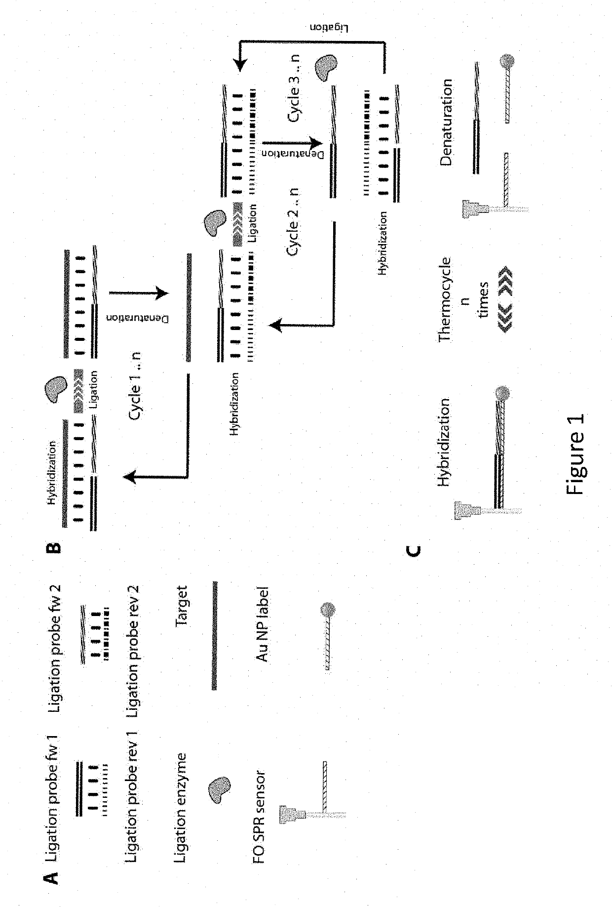
[0128]As described in FIG. 1, the FO-SPR LCR reaction consists of multiple ligation cycles, which are enabled by heating up and cooling down the reaction mixture. Because the heating of a fluid expands its volume, it also decreases the refractive index of the LCR reaction mixture, resulting in the SPR signal that is the exact inverse of the temperature signal (FIG. 6). This temperature effect is clearly visible in the FO-SPR signals on both measurement channels and allows easy processing of the data, as the refractive index changes can be used to determine the reaction cycle boundaries. Each reaction cycle is split in 3 phases, namely the hybridization phase where the DNA target strands can hybridize with the ligation probes, the ligation phase where the ligation enzyme covalently links perfectly hybridized probes and finally the melting phase where ligated products are melted from the target liberating it for the next round of ligation. The essential part of the LCR DNA ampl...

example 3

ation of DNA Targets Using the FO-SPR LCR Assay

[0130]Next, the FO-SPR LCR assay was used to determine the target concentration by examining the number of LCR cycles necessary to obtain a FO-SPR melting point of the corresponding DNA target. In FIG. 8 part A, the concept is shown for a WT DNA target concentration of 100 fM. Out of 40 LCR cycles performed, no clear melting point was observed for this target in the first 27 cycles. In the subsequent cycles, a melting point appeared first at 51° C. followed by gradual increase towards 52.3° C. This shift in Tm is expected and can be attributed to the dependence of Tm on the increasing target concentration through LCR cycles [Gudnason et al. Nucl. acids res., 2007, 35, e127]. In comparison with the Tm obtained during the DNA melting optimization experiments described in paragraph 4.2, the Tm has shifted almost 7° C., this is both a result from shorter hybridization times in the actual LCR assay and slight differences in ionic makeup of t...


PUM

PropertyMeasurementUnit
melting temperatureaaaaaaaaaa
diameteraaaaaaaaaa

Abstract

A method and kits are provided for nucleic acid quantification and discrimination using surface plasmon resonance (SPR). The method provided is able to significantly enhance the detection limit and multiplex the discrimination assay using the melting properties of the target DNA on top of standard PCR reaction. By using the heating and cooling cycles of the polymerase chain reaction (PCR) or Ligation chain reaction (LCR), DNA is melted and hybridized onto the SPR sensor surface together with a nanoparticle label. Thus, during every cycle of DNA amplification, the quantity and type of target DNA can be monitored.

Description

FIELD OF THE INVENTION[0001]The invention relates to real-time detection, identification, and quantification of nucleic acids targets using a mass sensitive biosensor, such as a fibre optic surface plasmon resonance (FO-SPR) device, in combination with nucleic acid amplification reactions such as polymerase chain reaction (PCR) and ligation chain reaction (LCR).REFERENCE TO SEQUENCE LISTING SUBMITTED VIA EFS-WEB[0002]This application includes an electronically submitted sequence listing in .txt format. The .txt file contains a sequence listing entitled “19893-14-Sequence_Listing.txt” created on May 6, 2016 and is 6 bytes in size. The sequence listing contained in this .txt file is part of the specification and is hereby incorporated by reference herein in its entirety.BACKGROUND OF THE INVENTION[0003]The detection, identification, and quantification of nucleic acids are fundamental to many diagnostic tests for infection, disease, contaminants, and / or allergens. In these tests, the d...

Claims


Application Information

Patent Timeline
Patent Type & Authority Patents(United States)
IPC IPC(8): C12Q1/6825C12Q1/6851C12Q1/6862
CPCC12Q1/6851C12Q1/6825C12Q1/6862C12Q2565/628C12Q2537/143C12Q2563/137C12Q2531/113C12Q2563/155C12Q2531/137C12Q2561/113
Inventor LAMMERTYN, JEROENKNEZ, KARELDELPORT, FILIP
Owner FOX BIOSYST NV
Learn More