Optimization and control of material processing using a thermal processing torch

a technology of thermal processing and material processing, applied in the direction of plasma welding apparatus, manufacturing tools, electromagnetic radiation sensing, etc., can solve the problems of poor cutting quality, reduced cutting speed, and reduced consumable life, so as to prolong the consumable life, improve the cutting quality, and efficiently convey information

Active Publication Date: 2019-10-22
HYPERTHERM INC
View PDF209 Cites 0 Cited by
  • Summary
  • Abstract
  • Description
  • Claims
  • Application Information

AI Technical Summary

Benefits of technology

[0004]Thus, systems and methods are needed to detect incompatible consumables in a plasma arc torch. In addition, systems and methods are needed to automatically adjust torch operating parameters to enhance cutting quality and prolong consumable life. Specifically, systems and methods are needed to efficiently convey information among various components of a torch system to facilitate operation control and optimization.
[0010]In some embodiments, the signal device is located at a surface of the body to minimize heat exposure during torch operation. This surface can be adjacent to a cooling mechanism of the torch, remote from a plasma arc of the torch, or in an o-ring channel of the torch, or a combination thereof. The signal device can be shielded by another torch component to minimize exposure of the signal device to at least one of thermal energy, radiation, damaging gases, or high-frequency energy.

Problems solved by technology

Installing incorrect consumables into a torch can result in poor cut quality and decreased cut speed.
In addition, incorrect consumables can reduce consumable life and lead to premature consumable failure.
Even when correct consumables are installed in a torch, it can be difficult for an operator to manually configure and optimize torch operating parameters corresponding to the selected consumable set.
Moreover, it can be difficult for a torch component manufacturer to guarantee performance if aftermarket consumables are used in a torch system.

Method used


Image

  • Optimization and control of material processing using a thermal processing torch
  • Optimization and control of material processing using a thermal processing torch
  • Optimization and control of material processing using a thermal processing torch

Examples


Embodiment Construction

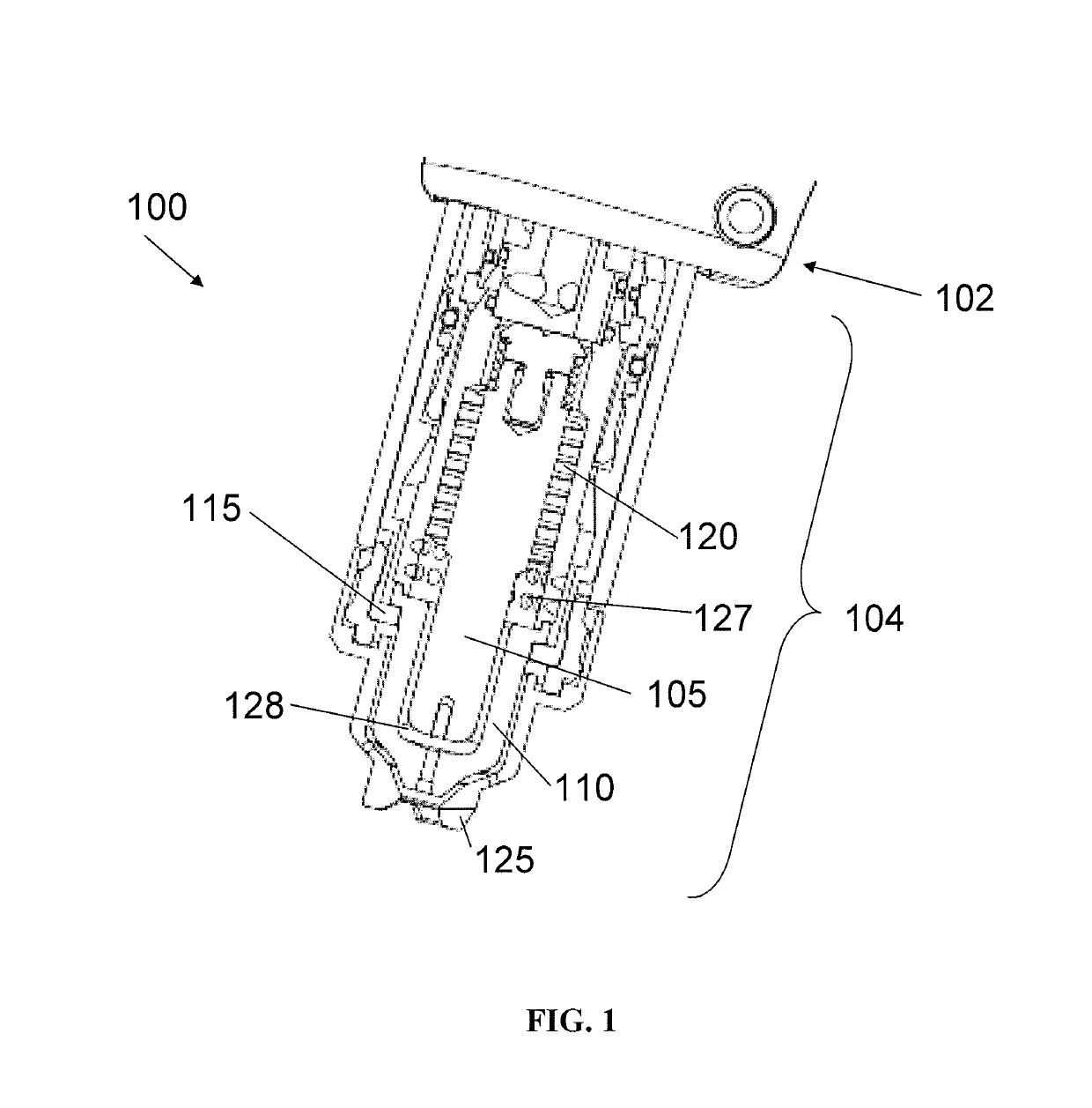
[0023]FIG. 1 is a cross-sectional view of an exemplary plasma arc torch 100 including a torch body 102 and a torch tip 104. The torch tip 104 includes multiple consumables, for example, an electrode 105, a nozzle 110, a retaining cap 115, a swirl ring 120, and a shield 125. The torch body 102, which has a generally cylindrical shape, supports the electrode 105 and the nozzle 110. The nozzle 110 is spaced from the electrode 105 and has a central exit orifice mounted within the torch body 102. The swirl ring 120 is mounted to the torch body 102 and has a set of radially offset or canted gas distribution holes 127 that impart a tangential velocity component to the plasma gas flow, causing the plasma gas flow to swirl. The shield 125, which also includes an exit orifice, is connected (e.g., threaded) to the retaining cap 115. The retaining cap 115 as shown is an inner retaining cap securely connected (e.g., threaded) to the nozzle 110. In some embodiments, an outer retaining cap (not sh...


PUM

PropertyMeasurementUnit
distanceaaaaaaaaaa
distanceaaaaaaaaaa
distanceaaaaaaaaaa

Abstract

A consumable component for a thermal processing torch is provided. The consumable component includes a consumable component body and a signal device located on or within the consumable component body for transmitting a signal associated with the consumable component. The signal can be independent of a detectable physical characteristic of the consumable component.

Description

FIELD OF THE INVENTION[0001]The present invention relates generally to controlling and optimizing material processing using signals associated with consumables of a thermal processing torch.BACKGROUND OF THE INVENTION[0002]Thermal processing torches, such as plasma arc torches, are widely used in the heating, cutting, gouging and marking of materials. A plasma arc torch generally includes an electrode, a nozzle having a central exit orifice mounted within a torch body, electrical connections, passages for cooling, and passages for arc control fluids (e.g., plasma gas). Optionally, a swirl ring is employed to control fluid flow patterns in the plasma chamber formed between the electrode and the nozzle. In some torches, a retaining cap can be used to maintain the nozzle and / or swirl ring in the plasma arc torch. In operation, the torch produces a plasma arc, which is a constricted jet of an ionized gas with high temperature and sufficient momentum to assist with removal of molten meta...

Claims


Application Information

Patent Timeline
Patent Type & Authority Patents(United States)
IPC IPC(8): G06K7/10B23K9/32H05H1/34B23K10/00
CPCB23K9/32H05H1/34B23K10/00H05H2001/3473H05H2001/3494H05H1/3473H05H1/3494
Inventor SHIPULSKI, E. MICHAELANDERSON, RICHARDBRAHAN, PETERCHIN, WAYNELIEBOLD, STEPHENBEST, GUYLINDSAY, JON
Owner HYPERTHERM INC
Why Eureka
Try Eureka