
Biomarker detection and self-separation of serum during capillary flow

a biomarker and capillary flow technology, applied in fluid controllers, laboratory glassware, instruments, etc., can solve the problems of inability to utilize other patient samples other than blood for diagnosis and monitoring, current state of the art biochips, and difficulty in detecting screening and monitoring in the early phase after onset, so as to reduce manpower and effort

Active Publication Date: 2019-11-19
NEW JERSEY INSTITUTE OF TECHNOLOGY
View PDF6 Cites 2 Cited by
  • Summary
  • Abstract
  • Description
  • Claims
  • Application Information

AI Technical Summary

Benefits of technology

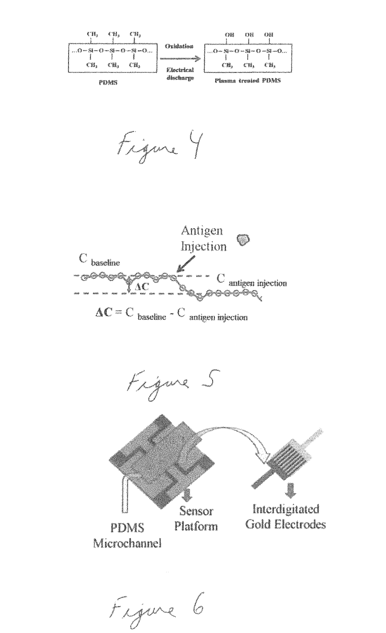
[0009]The above mentioned drawbacks are overcome and additional advantages obtained by the present disclosure. To achieve the early detection of a specific cancer type, the present disclosure includes a biochip that has a highly sensitive and specific set of antibodies and a sensing technology implemented. To increase the sensing capability, the biochip is fabricated with microchannels. The microchannel in the biochip is designed to control the flow mechanism and amplify the capillary effect of the blood flow. The flow is self-driven using the natural phenomenon called surface tension of the blood flow. Cancer antibodies with enhanced specificity and affinity are specially developed and ligated in the microchannel. When the blood sample flows in the microchannel over the cancer antibody, the cancer antigen from the blood forms antigen-antibody complex. This antigen-antibody interaction is captured using state of the art sensing technology and is developed using sophisticated nano circuit design in the biochip. The sensing methodology is a hybrid method of variation of capacitance charge. Also, the cancer severity is sensed depending on the intensity of the signal output. Therefore, the present disclosure can diagnose both the cancer and its severity using the micro biochip. Both qualitative and quantitative tests are used to test this novel sensing technology [1].
[0010]The novel state of the art sensing technologies applied in biochip can diagnose cancer both quantitatively and qualitatively. There are three ground breaking sensing technologies which are developed for cancer diagnosis, and also a hybrid method for implementing all these sensing technologies in the same chip is innovated to enhance its accuracy and reliability. The sensing technologies that are developed are: Temperature Variation, Variation Electric Oscillation, and Variation Capacitance Charge. Both cancer and its severity can be diagnosed using the micro biochip of the present disclosure.
[0011]The unique and exclusive characteristics of the biochip in sensing the antigen and antibody interaction are (1) the electrical sensing technology that is highly precise and accurate when compared to conventional optical sensing technology, (2) the quick response and instantaneous results with micro volume of blood sample, and (3) both qualitative and quantitative diagnosis of the cancer, which helps us diagnose the cancer with respect to each stage.

Problems solved by technology

However, the current state of the art biochips have many drawbacks.
For example, diagnosis including screening and monitoring in the early phase after onset is difficult with current health check-up sensitivity and specificity.
Furthermore some biochips lack the ability to utilize other patient samples other than blood, for example other bodily fluids such as urine, saliva, spinal fluid, and the like.
Also, some biochips are manufactured with glass that causes problems due to etching of the glass, cost of manufacturing, and extreme limitation of biochip construction.
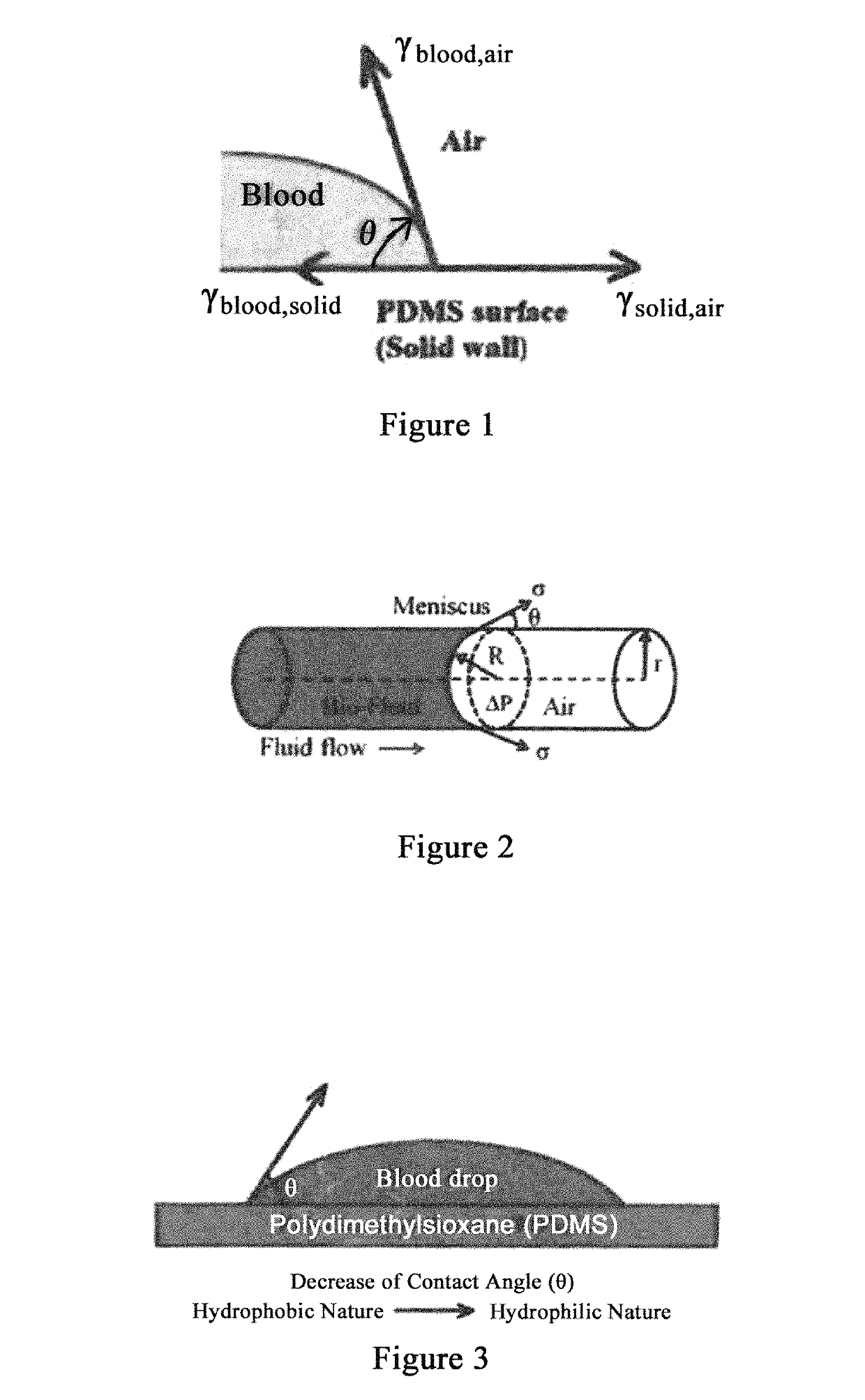
Use of other materials such as polymer based materials has failed due to the hydrophobic nature of the polymer material and its tendency for reducing the flow of any fluid.

Method used


Image

  • Biomarker detection and self-separation of serum during capillary flow
  • Biomarker detection and self-separation of serum during capillary flow
  • Biomarker detection and self-separation of serum during capillary flow

Examples


Embodiment Construction

[0064]In general, the present disclosure overcomes the disadvantages of past attempts and provides several other advantages. In addition, it also overcomes the disadvantages of past attempts to detect disease-specific antigens. As used herein, “sample” refers to a sample from a mammalian patient. Non-limiting examples of a sample include tissue or bodily fluids. Bodily fluids can include blood, urine, saliva, spinal fluid, any combination of these, or any other fluid originating in the body. Where blood is referenced specifically, it is referred to merely for illustrative purposes and is in no way meant to limit the scope of the invention.

[0065]Point of care (POC) micro biochip serves to diagnose cancer at earlier stages with its innovative and state of the art ‘sensing technology’ to identify the existence of cancer antibodies in the micro volume of blood sample with no external devices and no sample preparation. Some of the features of the present disclosure are as follows: (a) In...


PUM

PropertyMeasurementUnit
depthaaaaaaaaaa
widthaaaaaaaaaa
lengthaaaaaaaaaa

Abstract

Molecularly Imprinted Polymers (MIPs) are utilized to detect diseases and minimize false negative / positive scenarios. MIPs are implemented on a nano-electric circuit in a biochip where interactions of MIPs and an Antigen / Antibody (AG / AB) are detected, and disease specific biomarkers diagnosed. Biomarker detection is achieved with interdigitated gold electrodes in a biochip's microchannel. Capacitance changes due to biomarker interaction with AG / AB electrode coating diagnose diseases in a microfluidic environment. Biofluid passes through the microchannel and exposed to the nanocircuit to generate a capacitance difference and diagnose any specific disease in the biofluid sample. Blood capillary flow in a microchannel curved section experience centrifugal forces that separate liquid from solid. Various blood densities and segments experience different centrifugal effects while flowing through the curved section so serum is separated from various solid matter without using external devices.

Description

CROSS-REFERENCE TO RELATED APPLICATIONS[0001]The present application claims the benefit of the filing date of U.S. Provisional Patent Application No. 62 / 420,195 filed Nov. 10, 2016, U.S. Provisional Patent Application No. 62 / 420,226 filed Nov. 10, 2016, U.S. Provisional Patent Application No. 62 / 420,178 filed Nov. 10, 2016, the disclosures of which are hereby incorporated herein by reference.FIELD OF USE[0002]This disclosure relates to diagnostic assemblies to detect human diseases, such as cancer, and related pathogens. In particular, the present disclosure relates to a molecular imprinted polymer for biomarker detection using interdigitated electrodes in a biochip's microchannel having enhanced selectivity and sensitivity, and further relates to self-separation of serum during blood capillary flow through the microchannel.BACKGROUND[0003]Biochips are one technology currently under study to improve disease diagnosis. Biochips are defined as devices on which biomolecules such as DNA...

Claims


Application Information

Patent Timeline
Patent Type & Authority Patents(United States)
IPC IPC(8): G01N33/543G01N27/22G01N33/574B01L3/00G01N33/545
CPCG01N27/227G01N33/5438B01L3/502715G01N33/54373G01N27/226G01N33/574B01L3/502753G01N33/545G01N2600/00B01L2200/12B01L2200/143B01L2300/0636B01L2300/16B01L2400/0406B01L2300/0896B01L2400/0409B01L3/502746B01L2300/0645B01L2300/0819
Inventor LEE, EON SOONUNNA, BHARATH BABU
Owner NEW JERSEY INSTITUTE OF TECHNOLOGY
Learn More