High performance SRF accelerator structure and method

a technology of accelerators and superconducting radio frequencies, applied in accelerators, electrical equipment, etc., can solve the problems of limiting the ability to achieve a high q/sub>0/sub>, reducing the esub>acc/sub>, and no available techniques for producing srf cavities, etc., to achieve economic and efficient effect, cost reduction

Active Publication Date: 2019-11-19
JEFFERSON SCI ASSOCS LLC
View PDF11 Cites 4 Cited by
  • Summary
  • Abstract
  • Description
  • Claims
  • Application Information

AI Technical Summary

Benefits of technology

[0009]The second object of the invention is to provide a method for producing SRF cavities which eliminates or effectively removes the damage layer from the niobium cavity.
[0011]A further object of the invention is to provide a means of producing high Q0 and high Eacc cavities at reduced cost in a sustainable way using ingot niobium with relaxed specifications.
[0012]Another object is to enable the production of SRF cavities using ingot niobium of lower purity, thereby making this technology economical and efficient for industrial, nuclear energy and discovery science programs.

Problems solved by technology

Unfortunately, there are no available techniques for producing SRF cavities with both a high accelerating gradient (Eacc) and with a high quality factor (Q0).
Unfortunately, these methods tend to produce a damage layer within the niobium cavity which limits the ability to achieve a high Q0.
Under present methods, alloying with nitrogen and titanium improves the Q0 but unfortunately lowers the Eacc.

Method used


Image

  • High performance SRF accelerator structure and method
  • High performance SRF accelerator structure and method
  • High performance SRF accelerator structure and method

Examples


Embodiment Construction

[0018]The present invention is a method for producing high performance accelerator structures, such as SRF cavities, with high a quality factor (Q0) as well as high accelerating gradients (Eacc) using ingot niobium with relaxed specifications. The method eliminates the use of chemical polishing which loads the cavities with performance-degrading hydrogen.

[0019]SRF cavities quench at high magnetic field region (near the equator) due to first flux penetration where residual stresses are high and copious hydrogen is present. Magnetic flux reduces thermal conductivity and increases specific heat there by considerably reducing the thermal diffusivity. Thermal conductivity and specific heat data for niobium varies with different interstitials (purity of niobium) and process conditions.

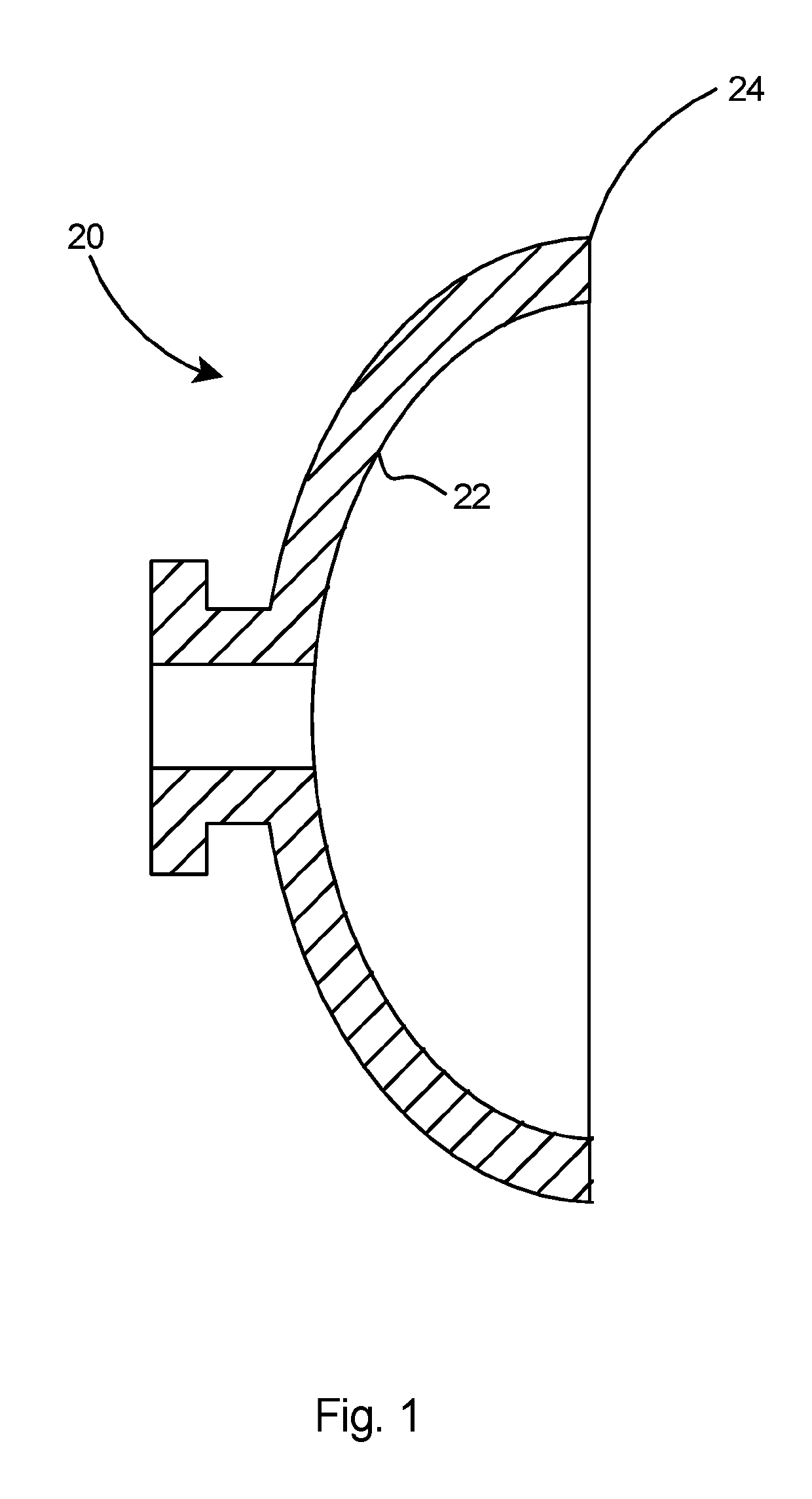
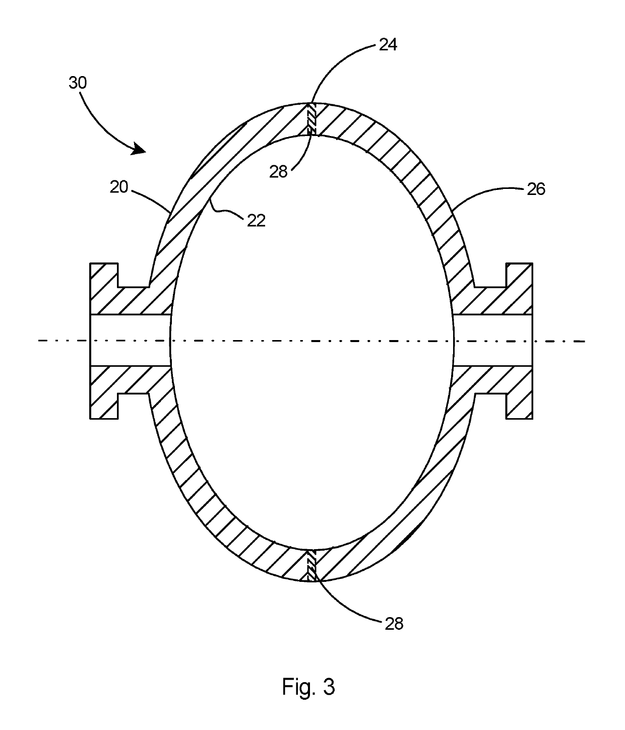
[0020]The preferred method of the present invention for forming accelerator structures with high quality factor and high accelerating gradients is the three dimensional (3D) machining of the half cells at a ...


PUM

PropertyMeasurementUnit
temperatureaaaaaaaaaa
RMS) roughnessaaaaaaaaaa
roughnessaaaaaaaaaa

Abstract

A high performance accelerator structure and method of production. The method includes precision machining the inner surfaces of a pair of half-cells that are maintained in an inert atmosphere and at a temperature of 100 K or less. The method includes removing thin layers of the inner surfaces of the half-cells after which the roughness of the inner surfaces in measured with a profilimeter. Additional thin layers are removed until the inner surfaces of the half-cell measure less than 2 nm root mean square (RMS) roughness over a 1 mm2 area on the profilimeter. The two half-cells are welded together in an inert atmosphere to form an SRF cavity. The resultant SRF cavity includes a high accelerating gradient (Eacc) and a high quality factor (Q0).

Description

CROSS-REFERENCE TO RELATED APPLICATIONS[0001]This application claims the benefit of Provisional U.S. Patent Application Ser. No. 62 / 281,846 filed Jan. 22, 2016.GOVERNMENT LICENSE RIGHTS STATEMENT[0002]The United States Government may have certain rights to this invention under Management and Operating Contract No. DE-AC05-06OR23177 from the Department of Energy.FIELD OF THE INVENTION[0003]The present invention relates to superconducting radio frequency (SRF) cavities and more particularly a method of producing SRF cavities having both high accelerating gradients and a high quality factor.BACKGROUND OF THE INVENTION[0004]Currently there are available techniques for producing SRF cavities with a high accelerating gradient and additional techniques for producing SRF cavities with a high quality factor. Unfortunately, there are no available techniques for producing SRF cavities with both a high accelerating gradient (Eacc) and with a high quality factor (Q0). The meaning of the term “hi...

Claims


Application Information

Patent Timeline
Patent Type & Authority Patents(United States)
IPC IPC(8): H05H7/20
CPCH05H7/20
Inventor MYNENI, GANAPATI RAO
Owner JEFFERSON SCI ASSOCS LLC
Why Eureka
Try Eureka