Support for multiple user defined assertion checkers in a multi-FPGA prototyping system

Active Publication Date: 2019-11-26
CADENCE DESIGN SYST INC
View PDF4 Cites 2 Cited by
  • Summary
  • Abstract
  • Description
  • Claims
  • Application Information

AI Technical Summary

Benefits of technology

[0005]In certain aspects, a computer-implemented method is described that includes selecting an assertion checker for a design under test, the design under test including hardware and firmware for a system on a chip. The computer-implemented method further includes instantiating the assertion checker in a compilation file, annotating the compilation file to define an assertion control signal for the assertion checker, and selecting one of a DISABLE or an ENABLE definition for the assertion control signal. In some embodiments, the computer-implemented method also includes configuring a clock in a prototyping platform to stop when the assertion control signal is enabled in the assertion checker and a logic condition for the assertion control signal is satisfied in the prototyping platform.
[0006]In certain aspects, a system is described that includes a memory storing instructions, and at least one processor that executes the instructions to propagate a stimulus waveform through a field programmable gate array board configured to execute a sub-netlist in a partition of a design under test in a prototyping platform, to turn control of the prototyping platform to a runtime system when an assertion checker is fired in the field programmable gate array board, and to call a user registered handler function in the runtime system to perform a diagnostic test of the design under test. Then at least one processor further executes instructions to possibly correct a local hardware or software condition in the sub-netlist based on the diagnostic test, and to return control of the design under test to the prototyping platform.
[0007]In certain aspects, a non-transitory, machine-readable storage medium is described that includes machine-readable instructions for causing a processor to execute a method.

Problems solved by technology

For large SoCs including multiple repetitions of smaller portions of circuitry, some emulators may require multiple circuits operating in parallel, thus increasing computational cost, packagi

Method used


Image

  • Support for multiple user defined assertion checkers in a multi-FPGA prototyping system
  • Support for multiple user defined assertion checkers in a multi-FPGA prototyping system
  • Support for multiple user defined assertion checkers in a multi-FPGA prototyping system

Examples


Embodiment Construction

[0017]The detailed description set forth below is intended as a description of various implementations and is not intended to represent the only implementations in which the subject technology may be practiced. As those skilled in the art would realize, the described implementations may be modified in various different ways, all without departing from the scope of the present disclosure. Accordingly, the drawings and description are to be regarded as illustrative in nature and not restrictive.

[0018]General Overview

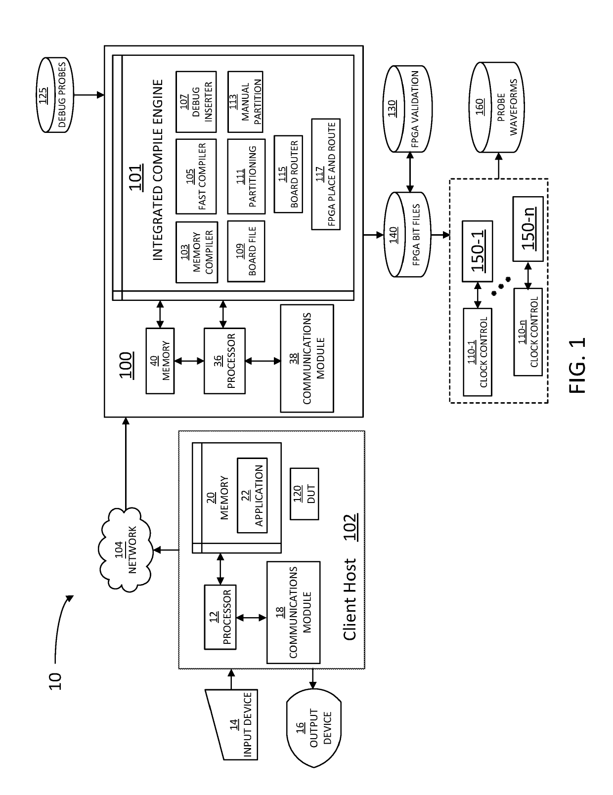
[0019]In some embodiments consistent with the present disclosure, FPGAs are used in prototyping and emulation platforms for SoCs. In some embodiments, a large register transfer level (RTL) file for an application-specific integrated circuit (ASIC, e.g., an SoC) is mapped to multiple FPGAs and the ASIC is simulated at the “silicon level” (e.g., transistor and other device properties). In addition, emulation platforms have built-in debug infrastructure and may be used for ea...


PUM


Abstract

A method is provided that includes selecting an assertion checker for a design under test. The design under test includes hardware and firmware for a system on a chip, the method including instantiating the assertion checker in a compilation file, annotating the compilation file to define an assertion control signal for the assertion checker, and selecting one of a DISABLE or an ENABLE definition for the assertion control signal. The method also includes configuring a clock in a prototyping platform to stop when the assertion control signal is enabled in the assertion checker and a logic condition for the assertion control signal is satisfied in the prototyping platform. A system and a computer readable medium including instructions to perform the above method are also provided.

Description

CROSS-REFERENCE TO RELATED APPLICATIONS[0001]This application is a divisional application of U.S. patent application Ser. No. 15 / 698,084 entitled “SUPPORT FOR MULTIPLE USER DEFINED ASSERTION CHECKERS IN A MULTI-FPGA PROTOTYPING SYSTEM,” and filed on Sep. 7, 2017, the disclosure of which is hereby incorporated by reference in its entirety.TECHNICAL FIELD[0002]Embodiments described herein are generally related to the field of prototype testing in circuit design applications. More specifically, embodiments described herein are related to methods for performing field programmable gate array prototyping of a system on a chip (SoC) design.BACKGROUND[0003]To test the capabilities and limitations of current SoCs, prototyping is a widely used technique. SoCs include complex circuitry (hardware) and control firmware, and prototyping techniques have been developed to verify hardware and software behavior and detect bugs, loopholes and other error conditions in the firmware, under different sti...

Claims


Application Information

Patent Timeline
IPC IPC(8): G06F17/50H03K19/177
CPCG06F17/5054G06F17/5027G06F17/5077H03K19/17736G06F30/34G06F30/331G06F30/394
Inventor RAMABADRAN, VASANT
Owner CADENCE DESIGN SYST INC
Why Eureka
Try Eureka