Wrappable multi-layer heat shield

a multi-layer, heat shield technology, applied in the direction of machines/engines, natural mineral layered products, braids, etc., can solve the problems of inefficiency, adverse effects of nitrogen oxide and carbon monoxide gases, and unwanted emissions

Active Publication Date: 2019-12-31
FEDERAL MOGUL POWERTAIN LLC
View PDF34 Cites 2 Cited by
  • Summary
  • Abstract
  • Description
  • Claims
  • Application Information

AI Technical Summary

Benefits of technology

[0006]In accordance with one aspect of the invention, a flexible, wrappable multilayered heat shield is provided. The heat shield includes a reflective outermost layer, an innermost layer of high temperature yarn, and an intermediate layer of nonwoven material sandwiched between the outermost and innermost layers. As such, the heat shield is composed of at least three different layers that protect one another in a way that allows each layer to function separately, as intended, and to further function together to provide a synergistic result that allows the heat shield, as a whole, to function as intended.
[0007]The heat shield is particularly useful as an exhaust system heat shield to facilitate optimal performance of a selective catalytic reduction system (SCR) within the exhaust system by minimizing the thermal losses of the high temperature exhaust gases flowing within the exhaust system. Accordingly, exhaust gases flowing throughout the SCR system of the exhaust system are maintained, by the heat shield, at a maximum temperature within the SCR system, with minimal temperature drop of the exhaust gases from that as first emitted from the engine. As such, an optimal chemical conversion of nitrogen oxide and carbon monoxide within the exhaust gases into nitrogen and water is achieved by the SCR system.

Problems solved by technology

However, in order for the SCR applications to perform efficiently, it is necessary for the exhaust gases that mix with the injected solution to remain at a maximum high temperature; otherwise, the intended chemical conversion of the nitrogen oxide and carbon monoxide gases is adversely affected and inefficient, thereby resulting in unwanted emissions thereof.

Method used


Image

  • Wrappable multi-layer heat shield

Examples


Embodiment Construction

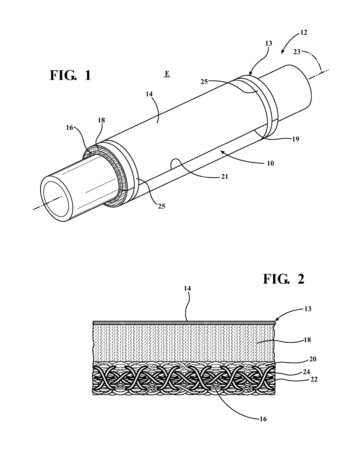
[0013]Referring in more detail to the drawings, FIG. 1 illustrates a wrappable, flexible multi-layered heat shield, referred to hereafter as heat shield 10, constructed in accordance with one aspect of the invention that provides desired shielding against thermal and other environment effects, such as to a shielded portion of an exhaust system, represented generally at 12, by way of example and without limitation. The heat shield 10 provides multiple shielding benefits, including, but not limited to, preventing the radiation of the high temperature exhaust gases within the exhaust system 12 to the outside ambient environment E, thus, preventing thermal losses of the high temperature exhaust gases; preventing thermal effects in the outside ambient environment E from reducing the temperature of the high temperature exhaust gases within the exhaust system, including external convection on the exhaust system, and further, preventing outside environment elements, such as fluids, from imp...


PUM

PropertyMeasurementUnit
temperaturesaaaaaaaaaa
temperatureaaaaaaaaaa

Abstract

A flexible, wrappable multilayered heat shield is provided. The heat shield includes a reflective metal outermost layer, an innermost layer of high temperature yarn capable of withstanding temperatures up to about 650 degrees ° C. continuously, and about 750° C. intermittently, and an intermediate layer of nonwoven material capable of withstanding temperatures up to about 550° C. continuously sandwiched between the outermost and innermost layers.

Description

CROSS-REFERENCE TO RELATED APPLICATION[0001]This application claims the benefit of U.S. Provisional application Ser. No. 61 / 869,859, filed Aug. 26, 2013, which is incorporated herein by reference in its entirety.BACKGROUND OF THE INVENTION[0002]1. Technical Field[0003]This invention relates generally to thermal heat shields, and more particularly to wrappable multilayer thermal heat shields.[0004]2. Related Art[0005]Standards for vehicle emissions are becoming increasing strict in reducing the emission of nitrogen oxide and carbon monoxide. In order to facilitate reducing the emission of these gases, many vehicle applications include selective catalytic reduction (SCR) applications, for example. SCR applications typically incorporate conduits for injecting ammonia or urea solutions into the exhaust pipe upstream of a catalytic converter. The injected solution evaporates and mixes with the exhaust gases to create a chemical reaction that will reduce nitrogen oxide and carbon monoxide...

Claims


Application Information

Patent Timeline
Patent Type & Authority Patents(United States)
IPC IPC(8): F01N13/16F01N13/18F02B77/11B32B5/04B32B5/10B32B5/12B32B5/22B32B5/26B32B7/00B32B7/02B32B7/10B32B9/00B32B15/00B32B15/01B32B15/04B32B15/14B32B15/18B32B15/20B32B19/04B32B19/06B32B1/00B32B1/04B32B1/08B32B3/00B32B3/02B32B3/04B32B3/06B32B5/02B32B5/00D04C1/06F01N13/14F01N3/20B32B7/027
CPCF01N13/18B32B1/00B32B19/06D04C1/06F02B77/11F01N3/2066F01N13/16B32B15/04B32B9/005B32B5/22B32B7/02B32B15/18B32B19/04B32B15/14B32B5/26B32B9/00B32B15/20B32B7/10B32B15/00B32B1/08B32B5/026B32B3/02B32B3/04B32B5/00B32B7/00B32B15/017B32B3/00B32B5/02B32B5/12B32B5/022B32B5/10B32B5/04F01N13/148B32B5/024B32B1/04B32B3/06Y10T442/60Y10T442/475Y10T442/488Y10T442/494Y10T442/3707Y10T442/656B32B7/027B32B9/047B32B2262/101B32B2307/304B32B2311/24
Inventor ZHANG, ZHONG HUAIGAO, TIANQILUDY, LINWOODROWCOTSKY, DANIELHO, WAI KIT
Owner FEDERAL MOGUL POWERTAIN LLC
Why Eureka
Try Eureka