Hollow core optical fiber and a laser system

a laser system and optical fiber technology, applied in the field of hollow core photonic crystal fiber and laser system, can solve the problems of difficult to launch pure lp01 mode without hom contamination, high leakage rate into the supporting solid glass sheath, anti-resonant hollow core fibers, etc., and achieve high suppression of homs and high spectral transmission.

Active Publication Date: 2020-01-07
NKT PHOTONICS
View PDF61 Cites 10 Cited by
  • Summary
  • Abstract
  • Description
  • Claims
  • Application Information

AI Technical Summary

Benefits of technology

[0012]In an embodiment it is an object to provide a hollow core PCF which has a high spectral transmission and a high suppression of HOMs.
[0111]The pressure tube can in principle be of any material. In an embodiment the pressure tube is of a thermo-moldable material, e.g. a material which may be molded or drawn at a fiber drawing tower. Advantageously the pressure tube is of silica optionally comprising a polymer coating. In an embodiment at least the supply section of the pressure tube has an outer polymer coating and optionally the pressure tube length section is free of polymer coating. The polymer coating increases the pliability of the pressure tube and reduces the risk of rupture of the pressure tube.

Problems solved by technology

Another drawback of prior art hollow core anti-resonant fibers is that they are not purely single mode waveguides because they also support some higher-order modes (HOMs).
Since these HOMs often have a relatively low loss, it is very difficult to launch a pure LP01 mode without HOM contamination and further HOMs can be excited by bending or external stress.
The non-touching glass elements had modes which were tailored to ensure resonant phase-matched coupling to higher-order core modes, causing them to leak at a very high rate into the supporting solid glass sheath.

Method used


Image

  • Hollow core optical fiber and a laser system
  • Hollow core optical fiber and a laser system
  • Hollow core optical fiber and a laser system

Examples


example 1

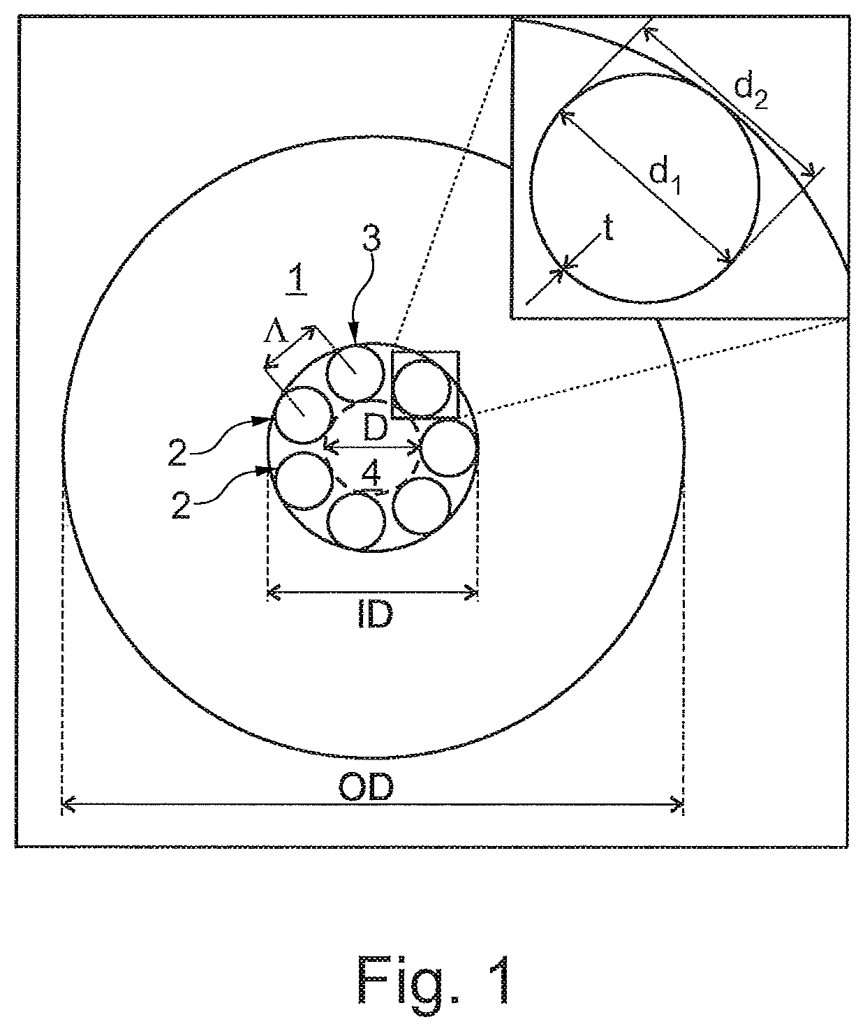
[0158]A hollow core PCF having a structure as shown in FIG. 1 was fabricated using the stack and raw technique. The fabricated fiber shown has a core diameter of approximately 30 μm, d2˜17 μm with a d2 / D˜0.57. The mode field diameter measured at 1064 nm is 2 2 μm. The tubes present minor size differences, nonetheless the fiber shows remarkable low loss and bend loss and good mode quality. The mode quality factor of the fabricated fiber was measured the mode quality factor with a camera—based M2 measurement system (Spiricon M2-2OOS) with a laser at a wavelength of 1064 nm and a 5 m FUT. We per-formed the measurements: with the fiber coiled on a standard 8 cm spool and no further coils. The results are summarized in Table I and shown in FIG. 14. The fiber output beam presents negligible astigmatism and asymmetry and a M2 of 1.2.

[0159]

TABLE 1AsymmetryAstigmatismM2 XM2 Y1.020.011.221.2


PUM

PropertyMeasurementUnit
diameteraaaaaaaaaa
thicknessaaaaaaaaaa
distanceaaaaaaaaaa

Abstract

A hollow core photonic crystal fiber (PCF) comprising an outer cladding region and 7 hollow tubes surrounded by the outer cladding region. Each of the hollow tubes is fused to the outer cladding to form a ring defining an inner cladding region and a hollow core region surrounded by the inner cladding region. The hollow tubes are not touching each other, but are arranged with distance to adjacent hollow tubes. The hollow tubes each have an average outer diameter d2 and an average inner diameter d1, wherein d1 / d2 is equal to or larger than about 0.8, such as equal to or larger than about 0.85, such as equal to or larger than about 0.9.Also a laser system is disclosed.

Description

TECHNICAL FIELD[0001]The invention relates to a hollow core photonic crystal fiber and a laser system comprising such hollow core optical fiber.BACKGROUND ART[0002]Hollow core photonic crystal fibers (PCF) have been known for many years and in some applications are very attractive to use compared to solid core PCF due to their very low propagation loss, low nonlinear effects and high damage threshold.[0003]A hollow-core fiber is an optical fiber which guides light essentially within a hollow region, so that only a minor portion of the optical power propagates in solid fiber material surrounding the core. The hollow region may be filled with air or any other gas or it may be evacuated to have a very low gas pressure.[0004]Over the years several types of hollow core PCFs have been developed, such as hollow-core photonic bandgap fibers e.g. as described in U.S. Pat. No. 6,892,018, Kagome design type fibers e.g. as described in U.S. Pat. No. 8,306,379.[0005]The kagome type fiber guides ...

Claims


Application Information

Patent Timeline
Patent Type & Authority Patents(United States)
IPC IPC(8): G02B6/02G02B6/42
CPCG02B6/02328G02B6/4296G02B6/02338G02B6/4206G02B6/02366G02B6/02371G02B6/02347C03B2203/14C03B2203/16C03B2203/42C03B37/0122H01S3/06708
Inventor LYNGSØE, JENS KRISTIANJAKOBSEN, CHRISTIANMICHIELETTO, MATTIA
Owner NKT PHOTONICS
Why Eureka
Try Eureka