Bubble-jetting member, gas-liquid jetting member, localized ablation device, and localized injection device

a bubble-jetting member and gas-liquid technology, which is applied in the field of bubble-jetting members, gas-liquid jetting members, localized ablation devices, and localized injection devices, can solve the problems of process targets adversely affected, bubble-jetting port sharpening, and damage to the tip section of the bubble-jetting member, so as to achieve easy operation and increase the collision energy of the jetted bubbles

Active Publication Date: 2020-01-21
JAPAN SCI & TECH CORP
View PDF7 Cites 0 Cited by
  • Summary
  • Abstract
  • Description
  • Claims
  • Application Information

AI Technical Summary

Benefits of technology

[0031]Because the tip section of the bubble-jetting member of the present invention is of increased thickness, the tip section of a localized ablation device using the bubble-jetting member or gas / liquid jetting member of the present invention is less likely to be damaged even when high voltage is applied thereto. Accordingly, the collision energy of the jetted bubbles can be increased, and localized ablation can accordingly be performed even on harder process targets. Also, because the bubble-jetting port of the bubble-jetting member can be made smaller when thickness-increasing processing is performed, the process target can be finely processed. Furthermore, because the tip of the bubble-jetting member can be formed flat, the process target is less likely to be adversely affected during localized injection.
[0032]The gas / liquid jetting member of the present invention is produced so that the bubble-jetting member and the outside shell part are capable of relative movement. Accordingly, positional adjustment of the process target and the bubble-jetting portion can be performed easily when performing localized ablation or localized injection on the process target using a localized ablation device or a localized injection device using the gas / liquid jetting member of the present invention. Furthermore, pressing the outside shell part against the process target during positional adjustment can prevent leakage of a conductive solution or a solution containing an injection material, and allows the positional relationship between the bubble-jetting member and the process target to be adjusted in that state. Therefore, the localized ablation device or the localized injection device of the present invention can be used in open air, and accordingly can be used, for example, as a needleless injection device.

Problems solved by technology

However, a new problem arose that the tip section of the bubble-jetting member will be damaged when high voltage is applied to the bubble-jetting member described in Patent Document 1.
However, a new problem arose that because the bubble-jetting member is made by pulling glass off, etc., the bubble-jetting port becomes sharp and the process target adversely affected during localized injection.
Furthermore, with the gas / liquid jetting member described in Patent Document 1, because the outside shell part is fitted on the outside of a positioning washer fitted on the bubble-jetting member, the distance between the bubble-jetting port of the bubble-jetting member and the tip of the outside shell part cannot be changed.
Therefore, a new problem arose that bubbles in which a solution containing an injection material is adsorbed on the boundaries thereof (referred to below as “gas / liquid”) lose energy by the time of reaching the process target, and the gas / liquid may be repelled by the process target depending on the process target.
Therefore, although it may be necessary to raise the voltage applied to the bubble-jetting member to increase the collision energy of the gas / liquid, a new problem arose that the tip section of the bubble-jetting member gets damaged when high voltage is applied as mentioned above.

Method used


Image

  • Bubble-jetting member, gas-liquid jetting member, localized ablation device, and localized injection device
  • Bubble-jetting member, gas-liquid jetting member, localized ablation device, and localized injection device
  • Bubble-jetting member, gas-liquid jetting member, localized ablation device, and localized injection device

Examples


example 1

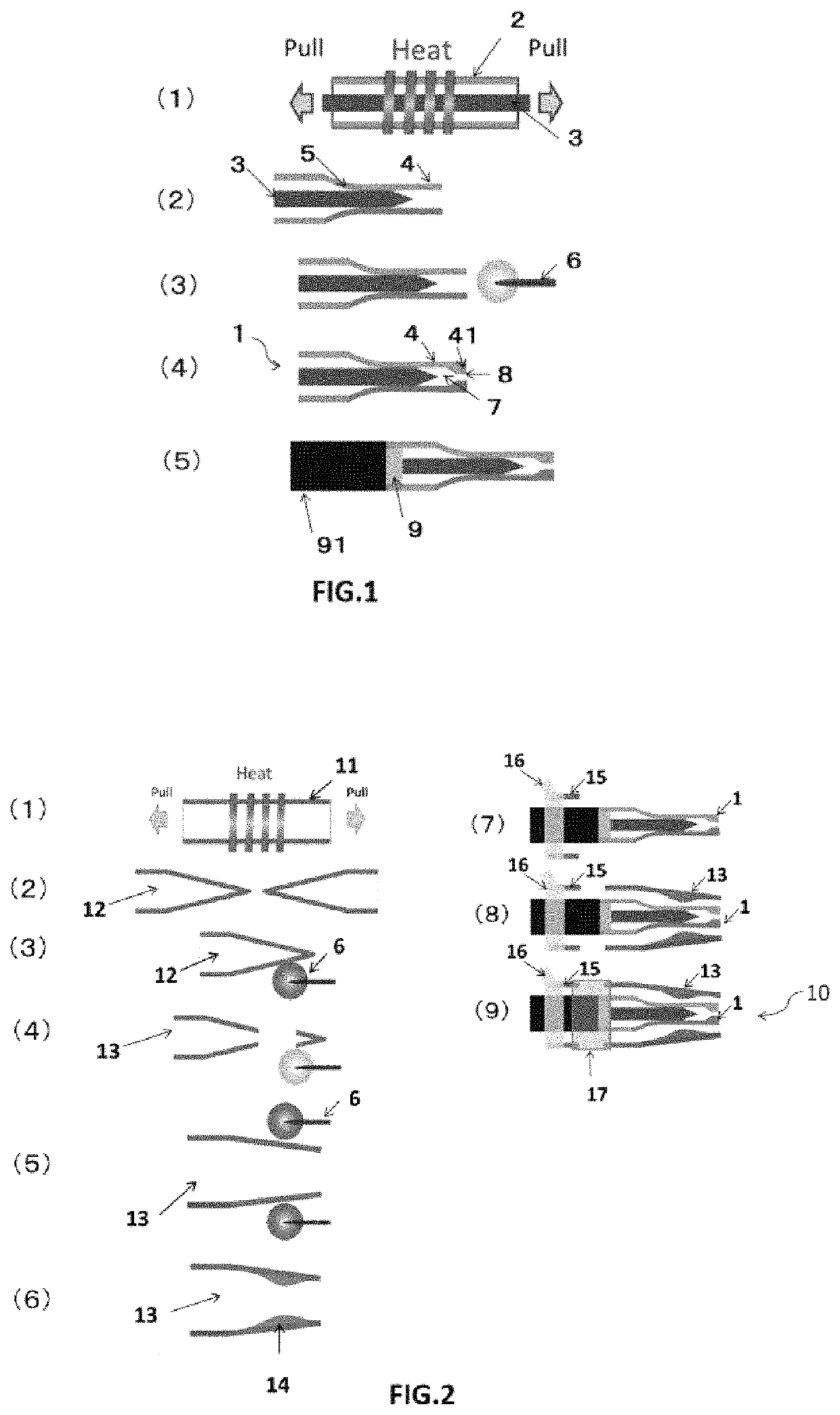
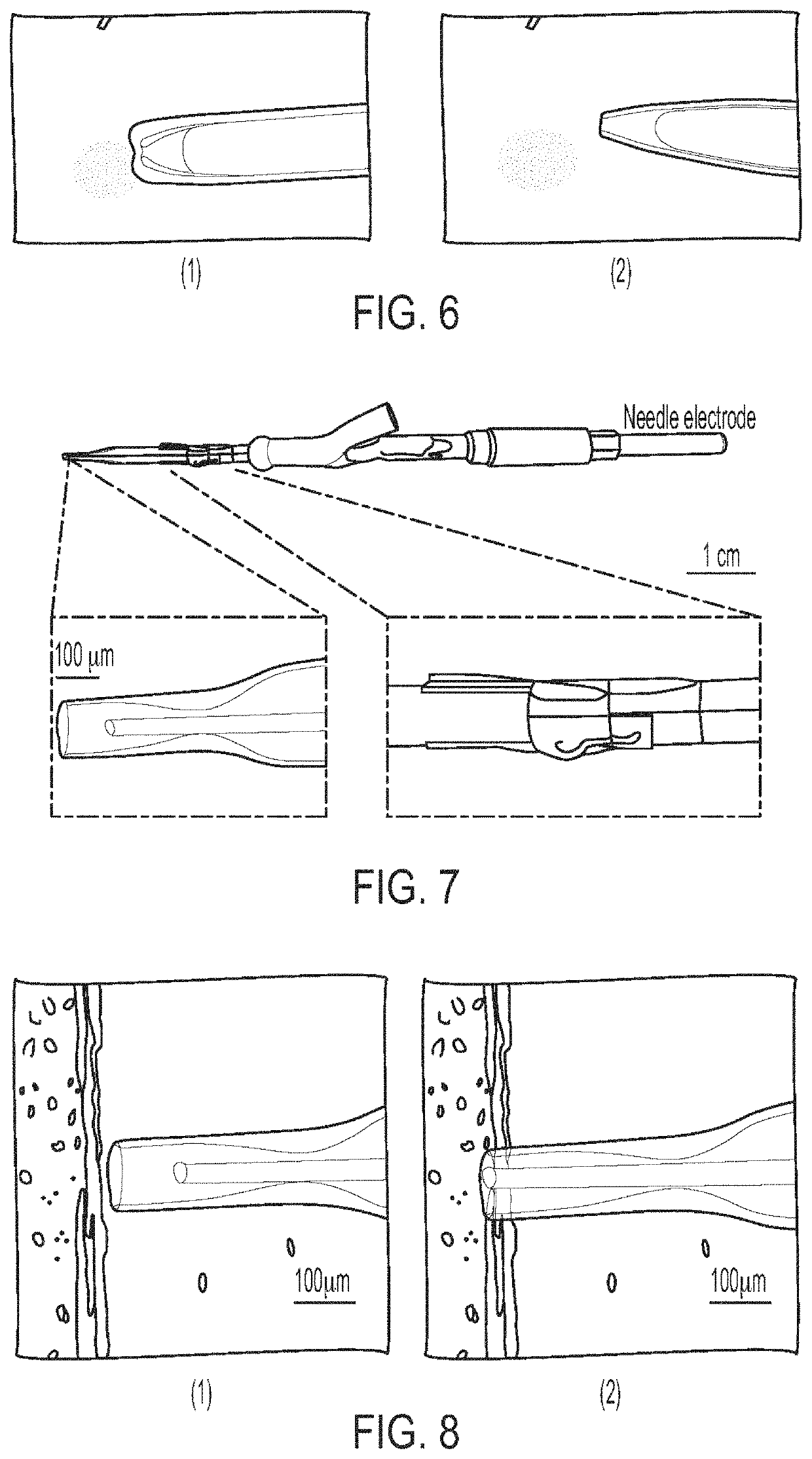
[0092]Cu wire having a diameter of 30 μm was inserted into a borosilicate glass tube for micropipettes (outer diameter 1.37 mm, inner diameter 0.93 mm, Drummond Scientific Company), and the glass tube was pulled apart under heating using a glass puller (P-1000IVF, product of Sutter Co.), whereby the glass was stretched from the Cu wire. Next, a thick portion was formed by pushing in the tip section of the stretched glass while melting using a microforge (MF-900, Narishige Co.), and a bubble-jetting member 1 of the present invention was thus produced. FIG. 6(1) is a photograph of the tip section of the bubble-jetting member 1 produced in example 1. As is clear from the photograph, it could be confirmed that the inside of the extended section 4 was formed thick in a tapered form going toward the tip. Also, the diameter of the core 3 was about 30 μm, and the bubble jetting port 8 was circular having a diameter of about 6 μm.

example 2

[0095](1) Production of Outside Shell Part 13

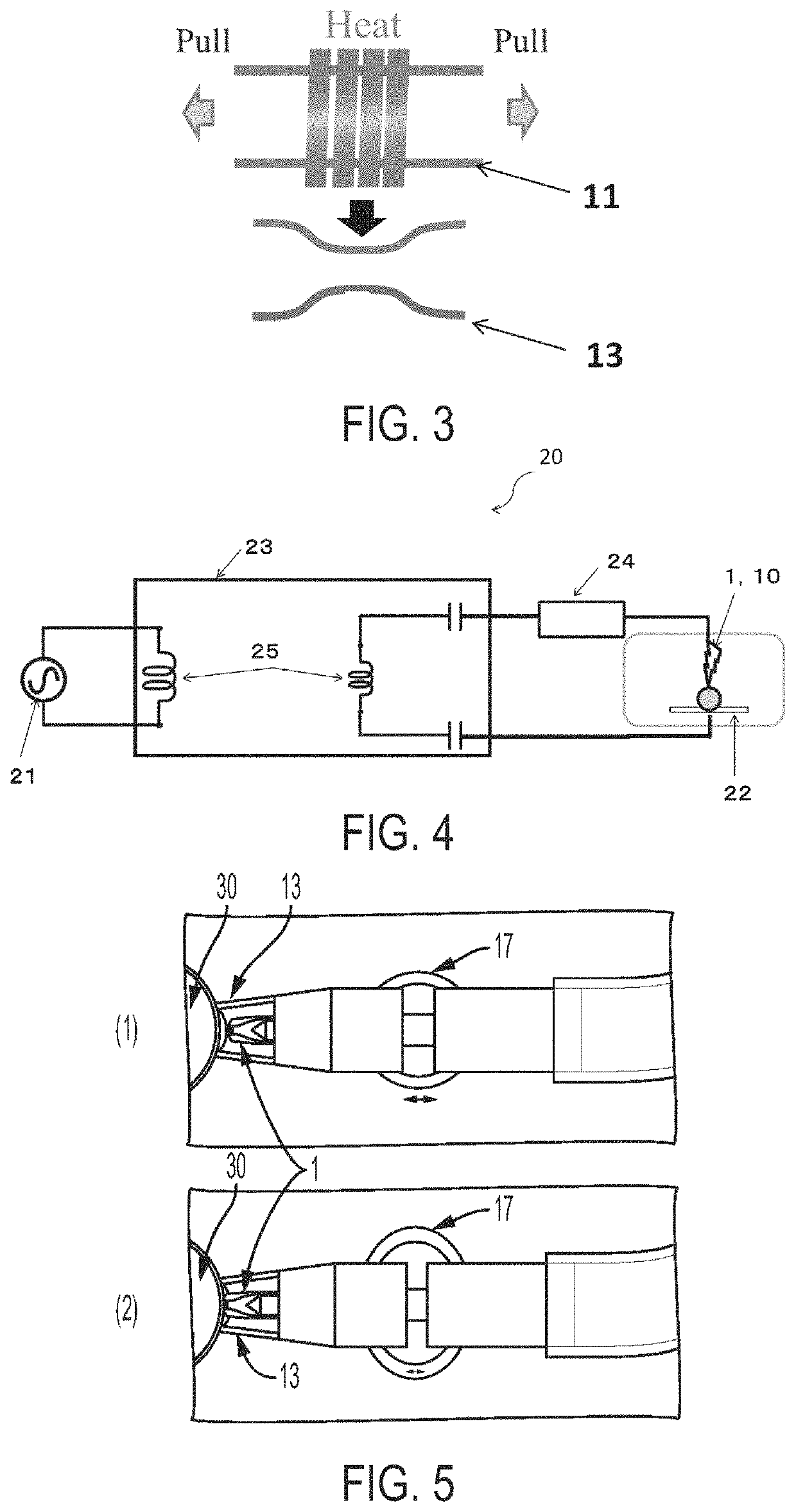
[0096]A borosilicate glass tube for micropipettes (outer diameter 2.03 mm, inner diameter 1.68 mm, Drummond Scientific Company) was pulled apart under heating using a glass puller (product of Sutter Co., P-1000IVF). The pulled apart glass tube was set in a microforge (MF-900, Narishige Co.), and the tip was cut to a diameter of about 100 μm. Furthermore, constricted portions 14 were produced by placing the microforge in contact at a position about 300 μm back from the tip and heating four places at 90° intervals. The inner diameter of the tip section of the outside shell part 13 was about 100 μm.

[0097](2) Assembly of Localized Injection Device

[0098]First, the bubble-jetting member 1 produced in example 1 was connected to an electric scalpel for medical use (product of ConMed Corp., 714-S) using Ag paste (H20E, Rikei Corp.). Then, the connection part was cured by heating on a hot plate at 120° C. for 15 minutes.

[0099]Next, PDMS (solvent: c...

example 3

[0102](1) Production of Outside Shell Part 13

[0103]A borosilicate glass tube for micropipette (outer diameter 2.03 mm, inner diameter 1.68 mm, Drummond Scientific Company) was pulled using a glass puller (product of Sutter Co., P-1000IVF) while heating, a neck structure was created in the center, and both ends of the neck structure were cut to a suitable length, whereby an outside shell part 13 was produced. The inner diameter of the outside shell part 13 was about 1.6 mm.

[0104](2) Assembly of Localized Injection Device

[0105]Next, PDMS (solvent:curing agent=10:1) (Dow Corning Toray Co., Ltd.) having been vacuum defoamed for 30 minutes was poured to a height of about 3 mm in a plastic tray of about 7 cm×7 cm×3 cm, vacuum defoaming was further performed for 20 minutes, and then the PDMS was baked for 20 minutes. Then the cured PDMS was removed from the plastic container and bored using a biopsy punch (Kai Corp.) having a hole diameter of 8 mm, the center was further bored using a biop...


PUM

PropertyMeasurementUnit
diameteraaaaaaaaaa
diameteraaaaaaaaaa
voltageaaaaaaaaaa

Abstract

Provided is a bubble-jetting member, the tip section of which is not damaged even when high voltage is applied thereto.There can be provided a bubble jetting member comprising: a core that is formed of a conductive material; a shell part that is formed of an insulating material, includes an extended section that extends beyond the tip of the core, and is closely adhered at least partially to the core and covers the core; and a space that is formed between the extended section and the tip of the core and has a bubble-jetting port, wherein there is formed on the tip of the extended section a thick portion that is thicker than the rest of the extended section whereby the tip section is not damaged.

Description

BACKGROUND OF THE INVENTIONField of the Invention[0001]The present invention relates to a bubble-jetting member, a gas / liquid jetting member, a localized ablation device, and a localized injection device, and particularly relates to: a bubble-jetting member in which the tip of a conventional bubble-jetting member is processed to be thick whereby a bubble-jetting port is made smaller and the tip is unlikely to be damaged even when high voltage is applied thereto; a gas / liquid jetting member in which an outside shell part that is capable of relative movement with the bubble-jetting member is formed whereby the position of the bubble-jetting member when processing a process target can be adjusted easily; a localized ablation device that includes the bubble-jetting member or the gas / liquid jetting member; and a localized injection device that includes the gas / liquid jetting member.Description of the Related Art[0002]Advances in biotechnology witnessed in recent years have been accompani...

Claims


Application Information

Patent Timeline
Patent Type & Authority Patents(United States)
IPC IPC(8): C12M1/42A01G7/06A23L13/50A23L13/70C12N15/87C12N15/09
CPCC12N15/87A23L13/50A01G7/06C12M35/04A23L13/72A23V2002/00C12N15/09C12M3/006C12N15/89
Inventor YAMANISHI, YOKOTAKAHASHI, KAZUKIOMI, SHUN
Owner JAPAN SCI & TECH CORP
Why Eureka
Try Eureka