
Catalytic biogas combined heat and power generator

a biogas and combined technology, applied in the direction of greenhouse gas reduction, steam generation using hot heat carriers, sustainable manufacturing/processing, etc., can solve the problems of waste disposal, non-regenerability, and inability to re-generate for long-term applications

Active Publication Date: 2020-04-21
HWANG HERNG SHINN
View PDF34 Cites 2 Cited by
  • Summary
  • Abstract
  • Description
  • Claims
  • Application Information

AI Technical Summary

Benefits of technology

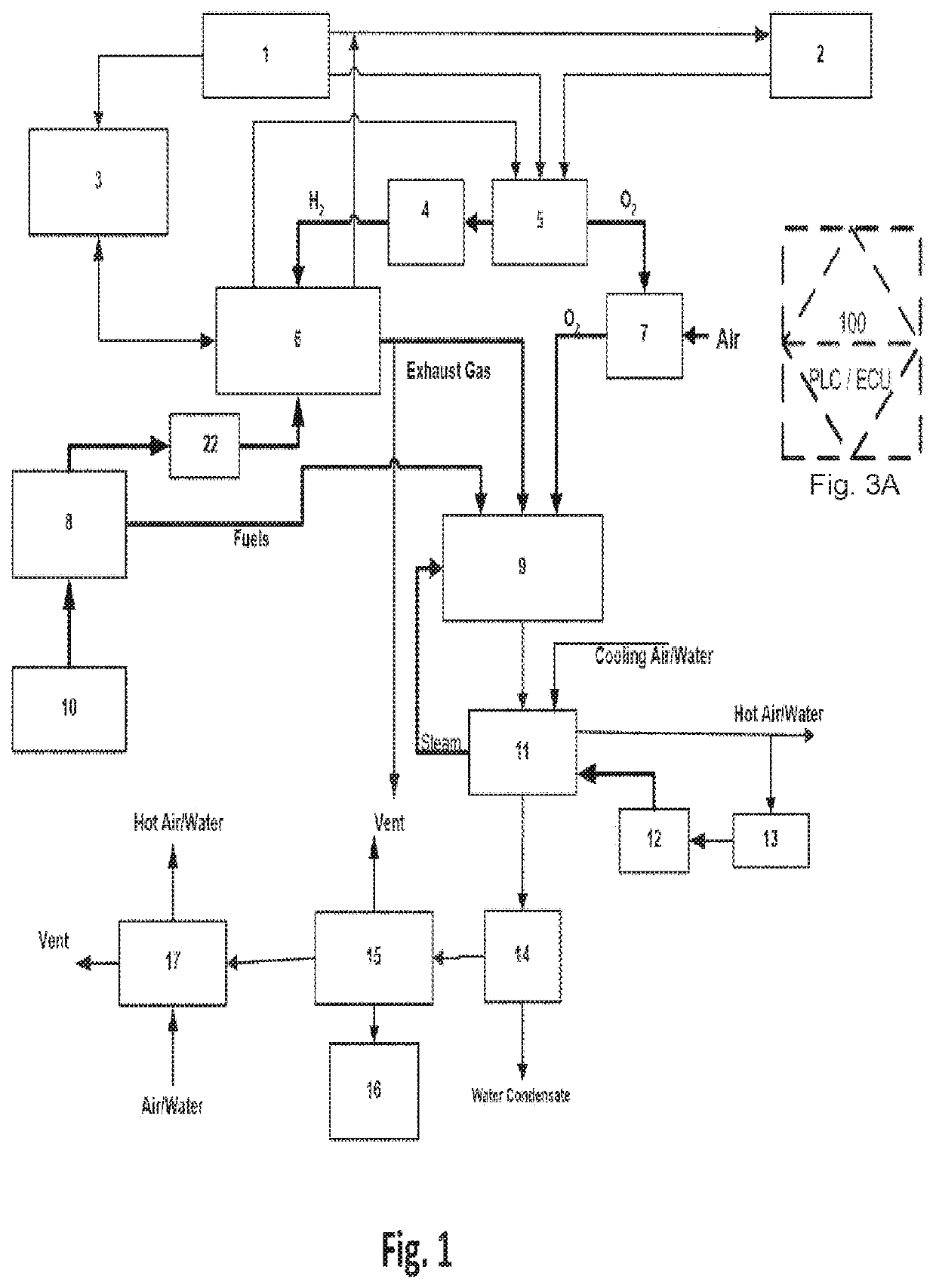
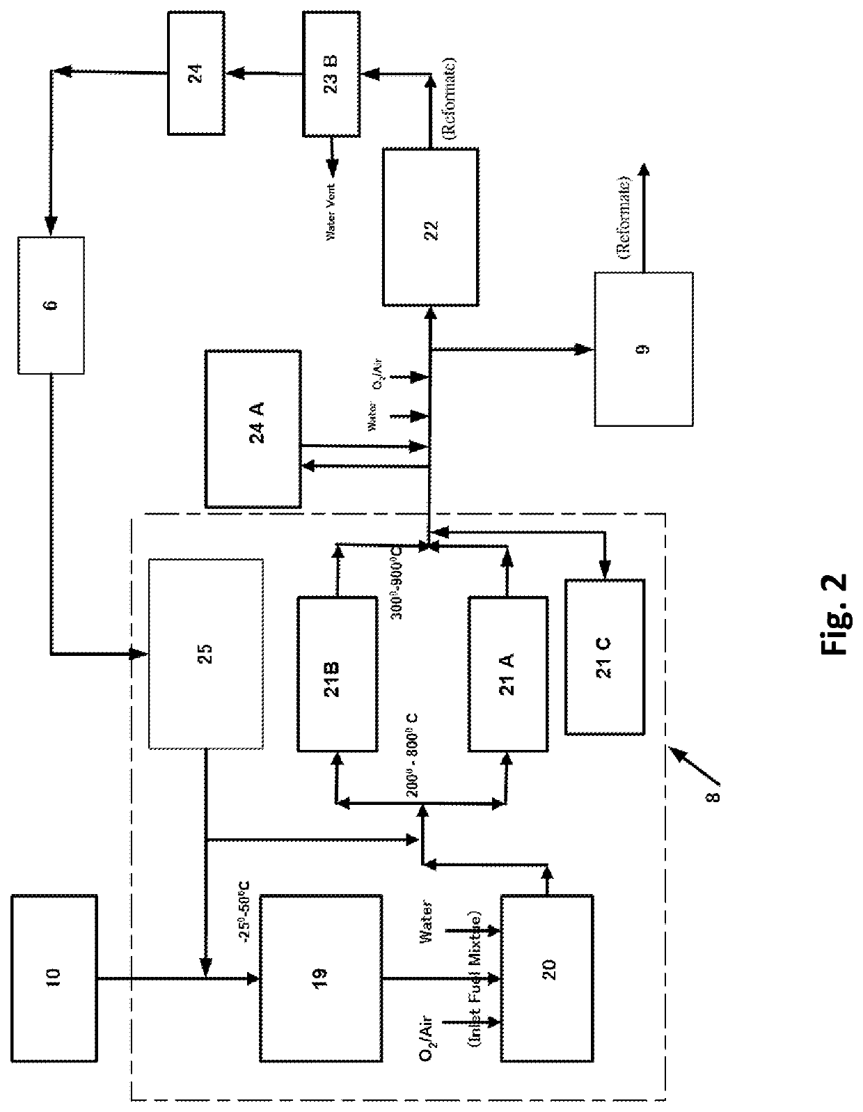
This patent describes a new system for using biogas from an anaerobic digester to provide heat and electricity to local residents. The system includes a new desulfurization system to remove sulfur compounds from the biogas. To increase the life of the catalyst and maintain high methane conversion, the reaction temperature must be controlled. The use of pure O2 and pure CH4 in the inlet fuel mixture can increase the concentration of H2+CO in the reformed gas generated by a CPO reformer and an ATR reformer. Using pure O2 to replace air as the reactant can improve the concentration of H2+CO close to that produced by the steam reforming reactions. Overall, this patent presents a new efficient and flexible system for using biogas for combined heat and power generation.

Problems solved by technology

However, if the above adsorbents are used, they either are non-regenerable or cannot be regenerated repeatedly for long term application.
Therefore, they have waste disposal problem once they reach their saturation capacity (Allegue and Hinge, Danish Technological Institute, December 2014).

Method used


Image

  • Catalytic biogas combined heat and power generator
  • Catalytic biogas combined heat and power generator
  • Catalytic biogas combined heat and power generator

Examples


Embodiment Construction

Description of the Preferred Embodiments

[0034]Because of the global warming and the abnormal worldwide weather pattern in recent years, it is wise to combine the renewable energy resources such as biogas, solar, wind and geothermal energies to cut down the carbon emission and to provide heat and electricity from biogas for daily living.

[0035]For this invention, a Catalytic Biogas Combined Heat and Power (CHP) Generator and method of operating this CHP generator comprises:

(1). one biogas storage tank at 1 to 100 atmospheres;

(2). one regenerable desulfurization system comprising:

[0036]a) one CPO sulfur converter for converting all sulfur compounds in the biogas over the supported Pt group metal catalyst into H2S at a temperature between 200° to 800° C., wherein the O2 / C ratio of the inlet fuel mixture is between 0.05 to 0.25, and the % (H2+Steam) in the gas mixture is between 0% to 20%, and[0037]b) one high temperature regenerable adsorbent bed at a temperature between 300° to 900° C....


PUM

PropertyMeasurementUnit
temperatureaaaaaaaaaa
concentrationaaaaaaaaaa
temperatureaaaaaaaaaa

Abstract

A distributed Biogas Combined Heat and Power (CHP) Generator can provide automatically hot water and electricity for local applications. Since biogas is produced by an anaerobic digester from human, animal, kitchen and agriculture's wastes, it is a short term recycled product from the photosynthesis of CO2, and has a net zero carbon emission. The sulfur compounds in the biogas can be removed by the following steps: (1), converting all sulfur compounds into H2S by the hydrogen produced from the biogas over Pt group metal catalysts; (2). adsorbing the H2S at high temperature by the regenerable Pt group metal catalyst and adsorbents. The desulfurized biogas is further converted by an ATR / CPO reformer or a steam generating reformer to produce various reformates, which can be connected to a downstream 1C engine / gas turbine, and / or a steam turbine to drive electric generators for generating electricity. The hot reformate and the exhaust gases can be cooled in heat exchangers to produce hot water / hot air.

Description

CROSS-REFERENCE TO RELATED APPLICATIONS[0001]This application claims priority under 35 U.S.C. § 119(e) to U.S. Provisional Patent Application No. 62 / 422,756, filed Nov. 16, 2016. The foregoing application is incorporated by reference herein.BACKGROUND OF THE INVENTION[0002]The CO2 in the atmosphere is constantly captured and converted through photosynthesis by various types of plants to produce human or animals' foods, such as sugar, starch, rice, wheat, potato, yam, grass, algae, vegetable, tree leaves, fruits et. al. After these foods are digested by human or animals, their excreta or the excess kitchen and agriculture's wastes can be used to produce biogas by an anaerobic digester, and the subsequent use of this biogas as a fuel for a combined heat and power (CHP) generator is realistically just returning the captured CO2 back into the atmosphere. In other words, the biogas is actually a short term recycled product of converting CO2 from one type of energy material into various o...

Claims


Application Information

Patent Timeline
Patent Type & Authority Patents(United States)
IPC IPC(8): F02B43/12F02M27/02F02D19/06C01B3/40C01B3/36C10L3/10F02B63/04G05B15/02F01K23/18F03D9/17F22B1/18F02B43/10
CPCC10L3/103C01B3/40F01K23/18G05B15/02F02D19/0644F02B63/04F02B43/12F02M27/02C01B3/36C01B2203/0244C01B2203/1064C01B2203/1035C01B2203/127C01B2203/1023C01B2203/0261F22B1/1838C10L2290/542F02B2043/106C01B2203/1241F03D9/17C10L2290/562C01B3/38C01B2203/0233C01B2203/0883C01B2203/169C01B2203/1082Y02P20/133Y02P20/584Y02P20/129Y02T10/30Y02E70/30Y02P80/10
Inventor HWANG, HERNG SHINN
Owner HWANG HERNG SHINN
Learn More