Devices and methods for quickly removing unwanted water from tanks

a technology for unwanted water and tanks, applied in liquid fuel feeders, machines/engines, separation processes, etc., can solve the problems of serious environmental damage, inconvenient transportation, and inability to quickly remove unwanted water from tanks, so as to reduce transportation costs and cleanup costs, reduce pollution, and facilitate transportation

Active Publication Date: 2020-05-12
THE ROSSI FAMILY TRUST DATED DECEMBER 20 2005
View PDF7 Cites 2 Cited by
  • Summary
  • Abstract
  • Description
  • Claims
  • Application Information

AI Technical Summary

Benefits of technology

[0093]America's petrochemical industry, including entities such as fueling facilities, and oil refineries, must become more efficient, and create less pollution, to continue to stay competitive. The WATER HOG makes gas stations and other fueling / fuel handling facilities more efficient in the follow ways. First, the WATER HOG is very easy to transport to the site where it is needed, which lowers transportation costs and cleanup costs directly, and therefore lowers operating costs. Second, the WATER HOG can in some iterations generally be reused, in principle, which makes use of WATER HOGs easier and cheaper for an entity that controls a fueling facility to use WATER HOGs to remove unwanted water from its Tanks. Third, some embodiments of the WATER HOG can be used to clean up other forms of pollution, or unwelcome heavy metals or other contaminants that might exist in a Tank. Fourth, the WATER HOG is simply a lesser “all-in” cost to produce, deliver, and use than many presently available alternatives, such as vacuum trucks. Fifth, the WATER HOG provides additional flexibility to fuel dispensing operators, in that the WATER HOG allows them to clean water out of their Tanks at times when few customers need to use their fueling locations. This results in fewer delays for customers, and more revenue for the fuel dispensing operator.
[0094]In a “gas station”, for example, above-ground fuel dispensers generally cannot be used by customers when a vacuum truck is removing water from the Tank from which that above-ground fuel dispensers draw fuel. The areas are generally “roped off” during the service process. This creates longer lines for customers, lower customer satisfaction, and lost revenue for the “gas station”, because customers who find that all of the above-ground fuel dispensers in a “gas station” are not available will sometimes go elsewhere.
[0095]Sixth, the “WATER HOG” helps operators of “gas stations” and other fuel dispensing locations to better preserve the value of their land, because the WATER HOG reduces the amount of hydrocarbon and other pollution that escapes into the land. If a piece of land has too high a level of hydrocarbon pollutants, that piece of land will become unsuitable for certain uses, like restaurants, for example. It the land is unsuitable for certain uses, the value of that land is lower than it would be otherwise. The WATER HOG reduces the amount of pollution that escapes into the land where a fuel dispensing location is located, therefore the WATER HOG helps to preserve the values of properties where fuel dispensing locations are located.
[0096]“Gas stations” and other fuel dispensing locations will also usually have a better idea of the amount of fuel in their Tanks if they often use WATER HOGs to remove unwanted water from the Tanks. Fuel dispensing locations that use WATER HOGs will therefore also reduce their costs because they will not need to have their Tanks unnecessarily refilled.
[0097]Use of the WATER HOG will therefore allow fuel dispensing locations to serve their customers better, and manage their inventories better, and also to hopefully increase their operating margins. This will enable fuel dispensing and fuel handling locations to lower prices they charge to any customers, and to potentially lower fuel prices. Customers will also benefit because they may experience lower fuel prices, and also fewer delays in waiting for vehicles to be refueled.
[0098]The WATER HOG can also be used more often than vacuum trucks, because the WATER HOG is less costly and easier to use than a vacuum truck, and also takes less time to use than a vacuum truck. This factor has many benefits for operators of fuel dispensing locations. One such benefit is that if water is removed from a Tank more often, this decreases the possibility of environmental harm and damage from phase separation or other corrosive effects, and also decreases damage to components such as valves, fittings, piping within the fuel dispensing system that result from corrosion. The WATER HOG can therefore help operators of fuel facilities to increase the lifespans of their equipment, and therefore decrease costs created by equipment repair and maintenance, thereby increasing profits, and / or decreasing the prices they charge to consumers.

Problems solved by technology

Accordingly, removing the water and separating it from the oil products is a problem in many situations, such as “gas stations”, and other fuel storage and dispensing locations, as explained below.
Further, current conventional methods for removing PCW consist of typically tubular absorbent socks that are extremely inefficient, largely because they cannot differentiate between water and hydrocarbons, so they absorb both in the same internal medium, as opposed to the current invention that accommodates easy extraction of water captured by the device in order to sharply reduce disposal handling and shipping costs.
This allows fuel from Under Dispenser Containers and fuel containers and piping leaks to enter the ground, causing pollution and serious environmental damage, and allows water from outside to intrude into the under-dispenser containers, the fuel dispensing system, or Tank, causing further damage.
Casey's invention also suffers from the disadvantage that Casey's invention is rigid, and therefore cannot adapt easily to turns in pipes and other rare characteristics of specific entities' fuel management infrastructure.
Imbiber Beads tend to be more costly than SAP as employed herein.
Phase separation can happen when water combines with alcohol (especially ethanol) to create a highly corrosive acid, which damages valves and other components of UDCs and Tanks.
These components may then have leaks, allowing petroleum products or other non-aqueous products contained within a UDC or Tank to be released into the environment.
These risks include damage to the petroleum infrastructure, damage to customer vehicles and station brand equity, and the potential to be left with unsaleable fuel.
The longer the water is there, present below the fuel in a Tank, the more of a chance that acid will spoil the fuel, or damage the Tank and / or related infrastructure and customer vehicle engines.
There are 3 main negative effects of phase separation:Damage to retail dispensing infrastructure.
The fluid resulting from phase separation is highly corrosive and can damage storage tank, submersible pumps, piping and fuel dispensers.Damage to customer vehicles and a gas station's brand.
Phase separation in most vehicles will cause engines to stall almost immediately, leaving disabled vehicles at the gas station.
This will cause a bad image problem and drop in customer loyalty which is hard to recover from.Out of spec or unsaleable fuel.
The result is a very slow flow of fuel out of the nozzle.
Filters reduce the damage, but they do not completely eliminate the potential to get phase separation in a vehicle.
By the time phase separation is detected by a dispenser filter, it has already accumulated in significant volume, leading to much larger remediation costs.
Dispenser filters need to be serviced and changed, and when such a filter is changed, there is a possibility that fuel will accidentally be spilled.
In the past, workers sometimes physically entered a drainage collection sump, but this has ceased because a person entering a drainage collection sump will be exposed to physically harmful substances such as contained in many oil products.
This is important because vacuum trucks generally visit “gas stations” during business hours, and use up space, so the consumers trying to purchase fuel at the “gas station” may not be able to do so or may be put at unreasonable risk or delayed.
Oil sheen is generally a very thin layer of hydrocarbons on the top of the water in the Tank and thus generally contains little oil albeit sheen still remains an unwanted and problematic presence in Tanks.
However, even though little attention has been paid to the characteristics of oil sheen in the past due to the difficulty of dealing with it, oil sheen may, in addition to encouraging phase separation, encourage a build-up of slime and other unwanted conditions in tanks, sumps, etc., in some instances by acting as a “glue” for accumulation / congregation of corrosion-causing acids and debris.
If there is ethanol in the Tank, phase separation is a resulting concern.
This in turn can lead to corrosion of plumbing, fittings, pumps, and other complications.
Oil sheen also forms petroleum-contaminated water (PCW) which cannot, in accordance with multiple governmental guidelines and laws, be allowed to seep or leak from tanks, etc., and find its way into the environment.
This also means that a large number of WATER HOGs can theoretically be quickly transported to a location where they need to be used in a situation such as a natural or man-made disaster, or in a situation where the roads or other transportation network leading to the location where the WATER HOGs are to be used is poorly developed or damaged.
A good example of this condition could be that following a hurricane, when water intrusion in Tanks can be very widespread and strain the ability of workers to remedy the situation before damage occurs to Tank systems.
Gravity or guidance by use of a pole or similar device will then cause the WATER HOG to sink until it contacts water.
There is sometimes a danger from pollution contained within water that is inside a Tank, where the pollutants will be carried by the liquids in the Tank if they escape the Tank.

Method used


Image

  • Devices and methods for quickly removing unwanted water from tanks
  • Devices and methods for quickly removing unwanted water from tanks
  • Devices and methods for quickly removing unwanted water from tanks

Examples


seventh embodiment

[0090]In a seventh embodiment, the WATER HOG can have one or more zippers, in each of the layers enclosing the SAP, so that a user who wishes to empty the SAP in the WATER HOG can unzip each of the zippers, and pour out the SAP. Then, if the user wishes to re-use the casings, and put “refill pouches” of SAP into the WATER HOG again later, the user may do so, and zip up the WATER HOG again. For example, the PC may have a zipper, and the containment skin may have another zipper.

[0091]WATER HOGS that contain other means of opening and reclosing the containment skin and PC to remove the SAP and add new SAP are explicitly part of the present invention.

[0092]Other embodiments of the WATER HOG are possible that combine characteristics of two or more of the embodiments described herein, and / or that have other characteristics presently known in the prior art.

Some More Advantages of the Water Hog Over the Prior Art

[0093]America's petrochemical industry, including entities such as fueling faci...

first embodiment

[0099]The first embodiment, and most other embodiments, of the WATER HOG can be disposed of after use in numerous ways, some of which are the following:

[0100]First, the user can cut open the WATER HOG, pour out the SAP, and allow the SAP to dehydrate. In embodiments with zippers, the user can use the zippers to open the layers of the WATER HOG that surround the SAP. Once the SAP has dried, it will have a fraction of the weight that the SAP had when it was wet. Therefore, the SAP can be disposed of much more easily and economically.

[0101]Second, the user can place the whole WATER HOG in a safe location where the WATER HOG can dry. The WATER HOG will then rapidly lose weight. The whole WATER HOG can be disposed of more easily because it will have lost most of its weight as the water evaporated.

[0102]Third, the user can dispose of the whole WATER HOG in accordance with local, state, and federal\ regulations. In most cases, the WATER HOG can be placed in a “Hazmat” container, which are ...

second embodiment

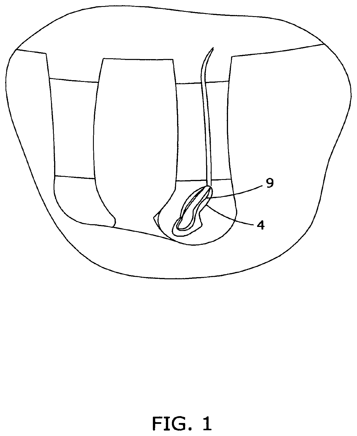
[0114]FIG. 1 shows a WATER HOG of the second embodiment inserted into a turbine sump. The fuel in the sump is floating on a layer of water that has accumulated there, in the lower areas of the turbine sump. Water is being absorbed into the WATER HOG. The matrix is exposed to the water.

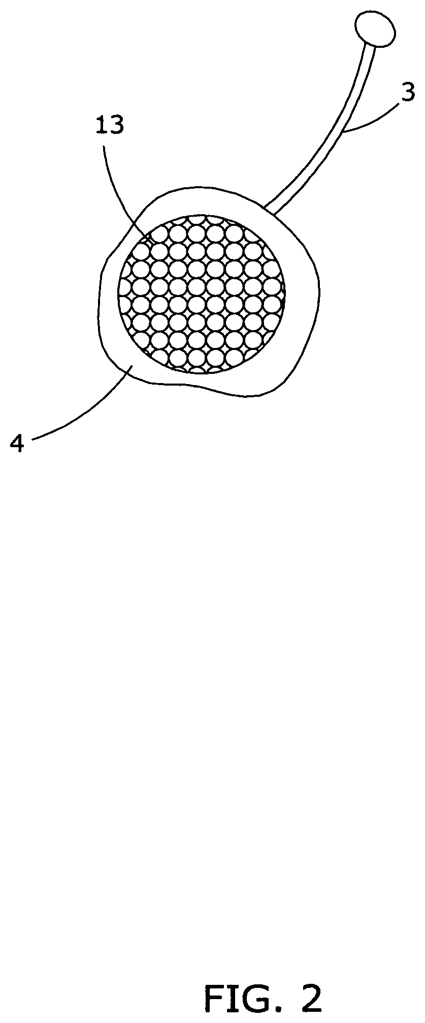
[0115]FIG. 2 shows a cross-section of a version of the first embodiment of the WATER HOG.

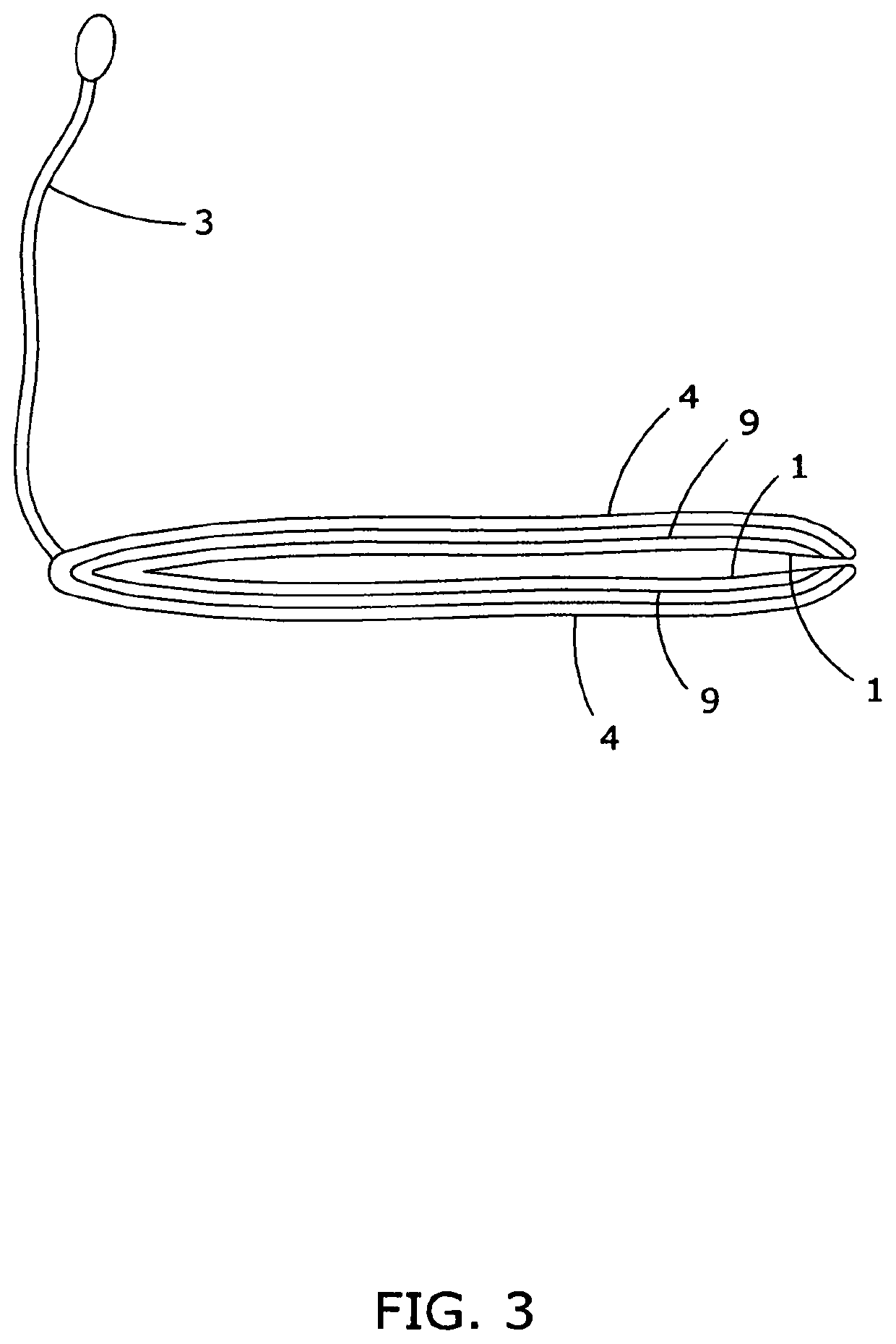
[0116]FIG. 3 shows a WATER HOG of the second embodiment, as it would appear when laid down.

[0117]FIG. 4 shows a WATERHOG with specialized microbes, inserted into the interstitial spaces between the walls of a fuel reservoir at a fueling facility.

[0118]FIG. 5 shows a WATER HOG being used together with several watery spill cleanup mats of the invention of U.S. Pat. No. 8,512,522, and a wall of water-activated FLOODBAGs of the invention of application Ser. No. 16 / 280,013. The WATER HOG is being used to remove a layer of water, and a layer of “sheen” in-between the pure water below and the oil products above. The water...


PUM


Abstract

The present invention includes iterations of devices for absorbing water and hydrocarbons that accumulate in hydrocarbon handling and dispensing systems, fuel tanks, sumps, and other oil and hydrocarbon storage tanks, at gas stations and other locations such as ports, commercial trucking facilities, government installations, military bases, privately owned and commercial shipping vessels, and privately maintained fueling locations including trucking facilities, etc. Specialized versions of the devices can also clean up petroleum slicks on water surfaces—known as “sheen” or petroleum-contaminated water (PCW”), and other contaminants. The present invention can stop “phase separation”. Once they have absorbed water, most versions of the device can also be disposed of easily and economically compared to alternative disposal methods due to their extremely light weight and because they can be dehydrated before disposal.

Description

STATE OF THE PRIOR ART[0001]Thomas Rossi, the inventor herein, is also the inventor of currently-pending U.S. application Ser. Nos. 16 / 280,013, and 14 / 617,355, and currently-pending PCT application PCT / US / 000025, and the specifications of all of those applications are hereby incorporated by reference.[0002]Pipes, sumps, turbine sumps, above and belowground fuel storage tanks including the main tanks as well as turbine sumps, interstitial spaces between the double walls of fuel storage tanks, “under dispenser containers” (“UDC”) that exist under fuel dispensers that serve to capture fuel commonly leaked from fuel supply lines and during the fueling or routine maintenance processes such as at a fueling facility (fueling facilities include, but are not limited to, “gas stations”) and other areas associated with fuel handling / dispensing, shall be collectively referred to herein as “Tank” or “Tanks”, and also fuel and oil storage tanks such as those in an oil refinery, port, or military ...

Claims


Application Information

Patent Timeline
Patent Type & Authority Patents(United States)
IPC IPC(8): B01D17/022F02M37/22B01D17/02F02M37/24
CPCB01D17/0202F02M37/24B60K15/03
Inventor ROSSI, THOMAS RALPH
Owner THE ROSSI FAMILY TRUST DATED DECEMBER 20 2005
Why Eureka
Try Eureka