
Nuclear power plant

a nuclear power plant and nuclear technology, applied in nuclear reactors, nuclear elements, greenhouse gas reduction, etc., can solve the problems of large amount of radioactive materials (fission products), waste heat recycling efforts, and damage to barriers blocking radioactive materials from an outside, so as to improve the efficiency and performance of heat exchangers, enhance economic efficiency, and enhance the reliability of safety systems

Active Publication Date: 2020-05-26
KOREA ATOMIC ENERGY RES INST
View PDF11 Cites 3 Cited by
  • Summary
  • Abstract
  • Description
  • Claims
  • Application Information

AI Technical Summary

Benefits of technology

The present patent aims to provide a nuclear power plant with a flexible design for a passive safety system that improves safety performance and economical efficiency. The heat exchanger in the safety system can be reduced in size, using electric power directly or through power generation to improve its efficiency. The safety system can also be powered by heat removed by the system, which ensures reliability without the need for emergency diesel generators or external power. The heat exchanger can also be configured to increase efficiency by using electric power for forced flow of fluids or for safety injection, spray, and cooling systems. Overall, the patent provides a comprehensive solution for enhancing safety and economical efficiency in nuclear power plants.

Problems solved by technology

First, a large amount of radioactive materials (fission products) are accumulated in a fuel rod as the reactor is operated.
Second, when the reactor is not properly cooled, barriers blocking radioactive materials from an outside may be damaged to leak the radioactive materials to the outside.
Third, even when the reactor is shut down, the fission products emit radiation and energy (decay heat) is generated at a fairly high level, requiring continuous cooling for a significant period of time.
However, in the existing passive safety system, heat removed to an outside of the containment is discarded to an external environment of the containment, and thus efforts to recycle such waste heat are required.
In addition, the passive safety system is very excellent in terms of safety because it is driven by natural power even when there is no emergency AC power or external power supply, but configuration options for designing the safety system are very limited, and a driving force of the system is typically very low, and thus there is a disadvantage of a high probability of reducing economic efficiency.
Furthermore, in case of a heat exchanger in a passive safety system, for example, a circulating flow of fluid inside or outside the heat exchanger depends on natural circulation mainly caused by a density difference, and thus there is a problem of reducing heat exchange performance.
In addition, according to a heat exchanger in a passive safety system, heat transfer is carried out between two fluids, and for example, when the types of two fluids are different, such as water or air, or the flow conditions of the two fluids are different, a size of the heat exchanger is determined by a fluid with a low heat transfer coefficient, and thus there is a problem of increasing the size of the heat exchanger.

Method used


Image

  • Nuclear power plant
  • Nuclear power plant
  • Nuclear power plant

Examples


first embodiment

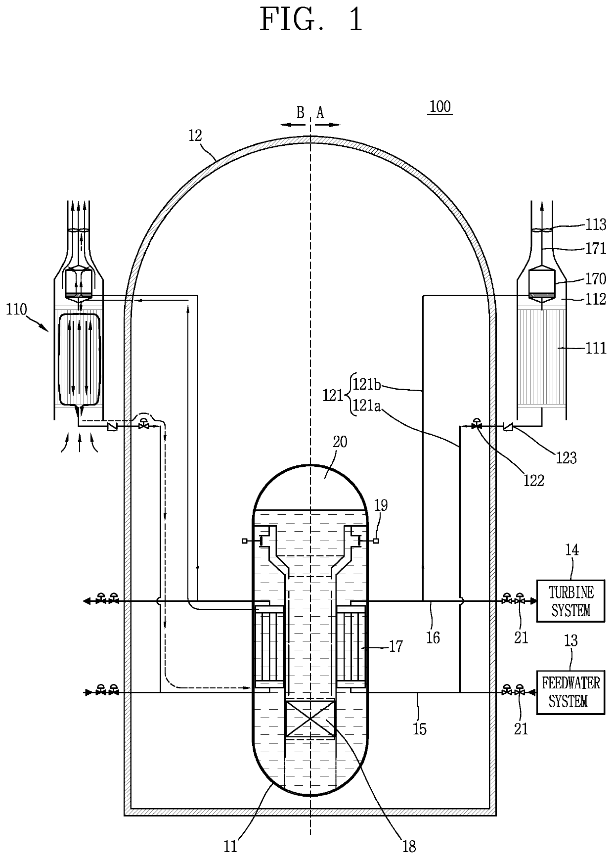
[0181]FIG. 1 is a conceptual view illustrating a passive residual heat removal system 110 to which a Stirling engine 170 according to a first embodiment of the present disclosure is applied, and a nuclear power plant 100 having the same.

[0182]Although the nuclear power plant 100 illustrated in FIG. 1 is illustrated for an integral type nuclear reactor, the present disclosure may not be necessarily limited to an integral nuclear reactor, and may also be applicable to a separate type nuclear reactor. Furthermore, the present disclosure may not be necessarily limited to a pressurized water reactor, and may also be applicable to various types of nuclear power plants including gas furnaces, liquid metal furnaces or the like.

[0183]According to the first embodiment of FIG. 1, for the sake of convenience of explanation, the passive residual heat removal system 110 and the nuclear power plant 100 having the same are illustrated symmetrically with respect to a reactor coolant system 11. A nor...

second embodiment

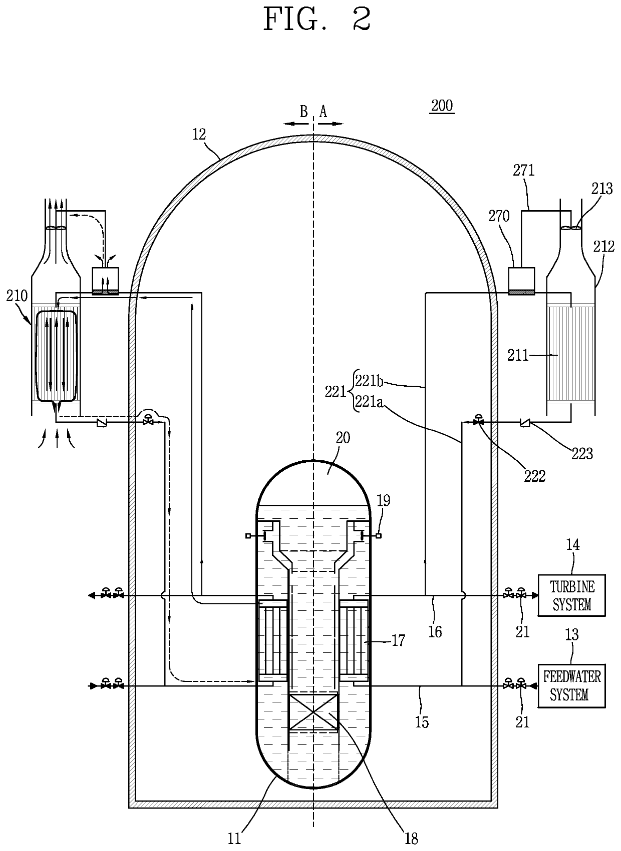
[0247]FIG. 2 is a conceptual view illustrating a passive residual heat removal system 210 to which a Stirling engine 270 associated with a second embodiment of the present disclosure is applied, and a nuclear power plant 200 having the same.

[0248]The Stirling engine 270 according to the second embodiment is provided at an outside of the containment 12 and an outside of a heat exchange casing 212. Other configurations are the same as or similar to those of the first embodiment described above, and thus the description thereof will be omitted for clarity of explanation.

[0249]However, when the Stirling engine 270 is exposed to an external environment of the heat exchange casing 212, it is easy for an operator's access, thereby having an advantage of facilitating maintenance.

third embodiment

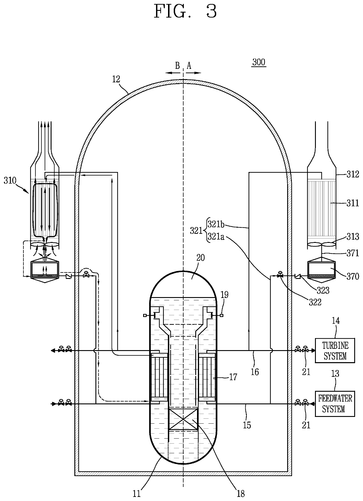
[0250]FIG. 3 is a conceptual view illustrating a passive residual heat removal system 310 to which a Stirling engine 370 according to a third embodiment of the present disclosure is applied, and a nuclear power plant having the same.

[0251]The Stirling engine 370 according to the third embodiment may be provided at a first flow path inlet side of a heat exchanger 311 and a second flow path outlet side of the heat exchanger 311 through which a cooling fluid is introduced. Steam introduced into the second flow path of the heat exchanger 311 may be cooled and condensed by the external atmosphere of the containment 12 introduced into the first flow path of the heat exchanger 311 and collected at the outlet side of the second flow path, and the collected cooling water may be transferred to the steam generator 17 along a feedwater pipe 321a. The Stirling engine 370 is provided on the feedwater pipe 321a to receive heat from the cooling water flowing along the feedwater pipe 321a so as to g...


PUM


Abstract

Disclosed is a nuclear power plant which drives a Stirling engine by means of heat generated in nuclear power plant safety systems during an accident, uses the resulting power directly or generates electric power so as to supply the power to the safety systems, and thus can improve economic efficiency as well as the reliability of safety systems, such as a passive safety system, by operating the safety systems without an emergency diesel generator or external electric power.

Description

CROSS-REFERENCE TO RELATED APPLICATIONS[0001]This application is the National Stage filing under 35 U.S.C. 371 of International Application No. PCT / KR2015 / 009498, filed on Sep. 9, 2015, which claims the benefit of earlier filing date and right of priority to Korean Application No. 10-2014-0126073, filed on Sep. 22, 2014, the contents of which are all hereby incorporated by reference herein in their entirety.BACKGROUND OF THE INVENTION1. Field of the Invention[0002]The present invention relates to a nuclear power plant, and more particularly, to a nuclear power plant capable of recycling heat to be removed from a nuclear safety system at the time of an accident into the operation of the nuclear safety system.2. Description of the Related Art[0003]Nuclear power plants produce electricity using heat generated by a reactor. A typical nuclear reaction occurring in a reactor is nuclear fission by uranium (U)-235 (atomic number 92, mass number 235). When neutrons collide with U-235 and are...

Claims


Application Information

Patent Timeline
Patent Type & Authority Patents(United States)
IPC IPC(8): G21C9/00G21D1/02G21C9/012G21C15/26G21C1/32G21C15/18G21D1/04G21D3/04G21C15/243G21C15/02F02G1/043
CPCG21C15/243G21C15/182G21C1/326G21C15/26G21D1/02G21C15/02G21D3/04G21C9/012G21D1/04F02G1/043G21C1/32Y02E30/40G21C15/185Y02E30/00Y02E30/30
Inventor KIM, YOUNG INCHOI, SUHNKIM, KEUNG KOOBAE, YOUNG MINHAN, HUN SIK
Owner KOREA ATOMIC ENERGY RES INST
Learn More