
Method of computed tomography imaging

a computed tomography and imaging technology, applied in the field of computed tomography imaging, to achieve the effect of enhancing the diagnostic value of liver imaging

Active Publication Date: 2020-06-02
KONINKLJIJKE PHILIPS NV
View PDF14 Cites 2 Cited by
  • Summary
  • Abstract
  • Description
  • Claims
  • Application Information

AI Technical Summary

Benefits of technology

This patent is about new techniques for improving the accuracy of liver imaging for surgery purposes. It describes using multiple contrast agents and K-Edge CT imaging to better visualize the structure of the liver and its blood supply. This helps to better prepare for surgery and reduces the risk of complications. The patent also describes the use of preoperative embolization of a segmental portal vein to induce hepatic ischemia and improve surgical outcomes. Finally, the patent describes storing partial blood volume maps in a database to help detect abnormalities on upcoming images and improve diagnosis quality. Overall, this patent offers new ways to enhance the diagnostic value of liver imaging for surgery preparation.

Problems solved by technology

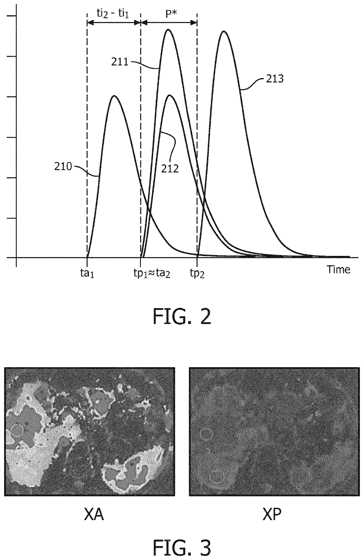
The problem is that a dedicated CT protocol for evaluation of liver lesions contains up to four scans: a native scan, without any contrast agent, a second scan in the “arterial phase”, when the contrast agent bolus just arrived in the arterial system, a third scan in the “portal venous phase” when the contrast agent bolus arrived through the portal vein, and a final scan when the system reached equilibrium.

Method used


Image

  • Method of computed tomography imaging
  • Method of computed tomography imaging
  • Method of computed tomography imaging

Examples


Embodiment Construction

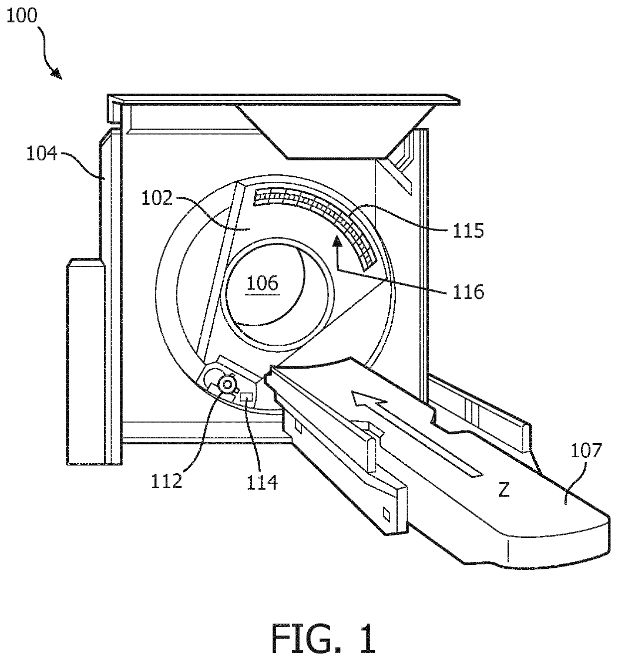
[0032]FIG. 1 schematically illustrates an example imaging system 100, such as a computed tomography (CT) scanner. The imaging system 100 includes a rotating gantry 102 and a stationary gantry 104. The rotating gantry 102 is rotatably supported by the stationary gantry 104. The rotating gantry 102 is configured to rotate around an examination region 106 about a longitudinal or z-axis. The imaging system 100 further includes a subject support 107 that supports a subject or object in the examination region 106 before, during and / or after scanning. The subject support 107 can also be used to load and / or unload the subject or object into or from the examination region 106. The imaging system 100 further includes a radiation source 112, such as an x-ray tube, that is rotatably supported by the rotating gantry 102. The radiation source 112 rotates with the rotating gantry 102 around the examination region 106 and is configured to generate and emit radiation that traverses the examination r...


PUM


Abstract

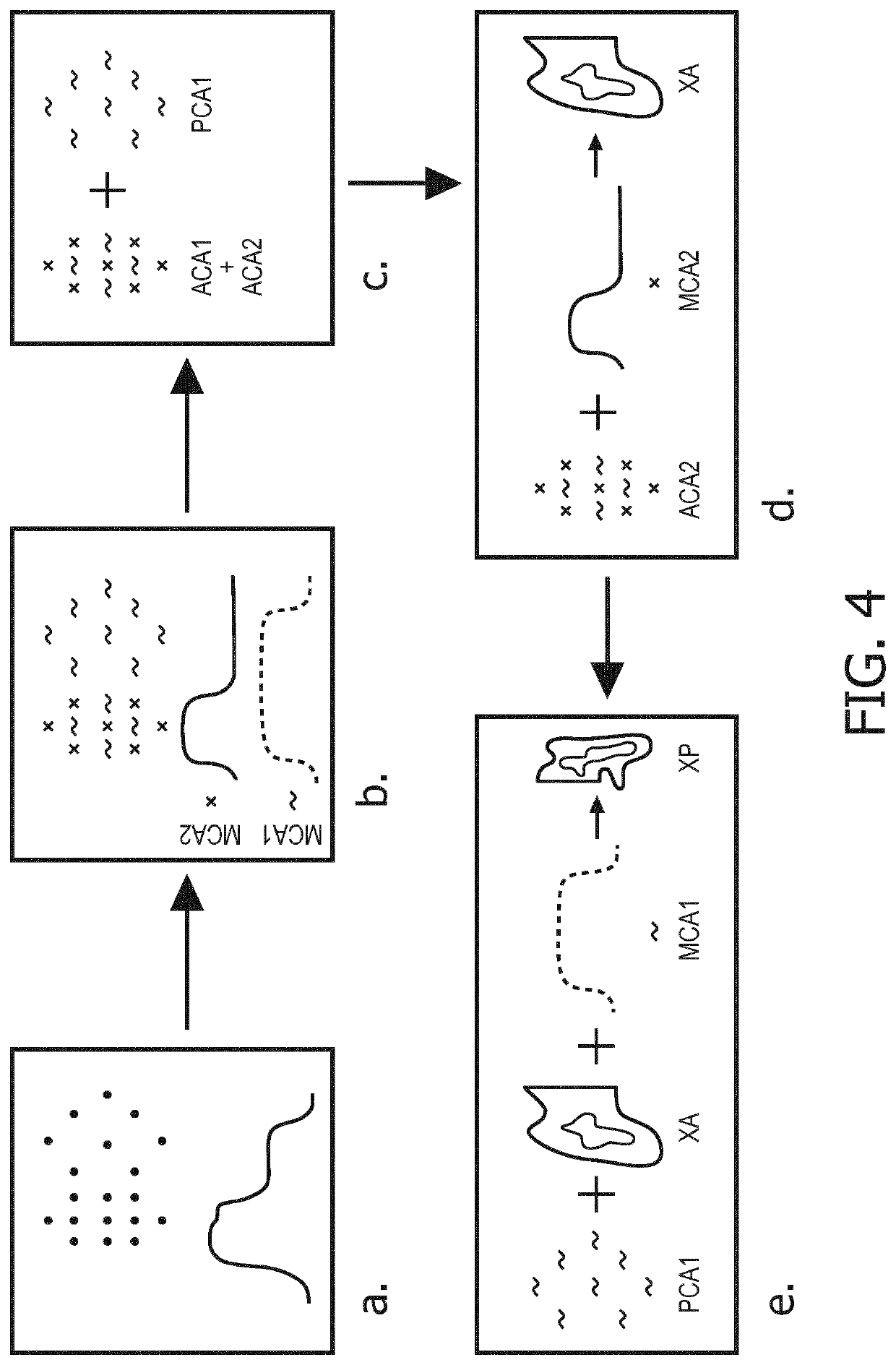
The invention relates to a method of Computed Tomography imaging comprising: a. Performing a single acquisition of image data from at least two contrast agents into a blood vessel network, a first contrast agent among said at least two contrast agents having been in said blood vessel network for a longer time than a second contrast agent among said at least two contrast agents, b. Processing said image data using K-Edge detection and / or iodine delineation to separate data associated with each contrast agents in order to obtain a concentration map of each contrast agent, c. Determining from said image data a first part of the blood vessel network comprising both the first contrast agent and the second contrast agent, and a second part of the blood vessel network comprising only the first contrast agent, d. Calculating a partial blood volume map of the first part of the blood vessel network based on the total amount of second contrast agent and on the concentration map of the second contrast agent, e. Calculating a partial blood volume map of the second part of the blood vessel network based on the total amount of first contrast agent, on the concentration map of the first contrast agent and on the partial blood volume map of the first part of the blood vessel network.

Description

CROSS REFERENCE TO RELATED APPLICATIONS[0001]This application is the U.S. National Phase application under 35 U.S.C. § 371 of International Application No. PCT / EP2016 / 076280, filed Nov. 1, 2016, published as WO 2017 / 080866 on May 18, 2017, which claims the benefit of European Patent Application Number 15193957.6 on Nov. 10, 2015. These applications are hereby incorporated by reference herein.[0002]The invention relates a method and device to the field of medical imaging. It finds particular application to computed tomography (CT) angiography, especially for liver imaging.BACKGROUND[0003]Liver cancer is a major disease with about 750,000 death per year. Multi-phase Liver CT imaging is a major tool for diagnosis, staging and treatment monitoring. Multiple phases of the contrast agent dynamics are imaged and used to identify different lesion types. The liver has two blood supplies: the hepatic artery and the portal vein. As such, a contrast agent which has been injected at a given time...

Claims


Application Information

Patent Timeline
Patent Type & Authority Patents(United States)
IPC IPC(8): G06K9/00A61B6/03A61B6/00
CPCA61B6/507A61B6/481A61B6/50A61B6/032A61B6/5205A61B6/482A61B6/504A61B6/4241A61B6/486
Inventor PROKSA, ROLANDDAERR, HEINERMUENZEL, DANIELANOEL, PETER
Owner KONINKLJIJKE PHILIPS NV
Learn More