Method of cleaning electrostatic chuck

a technology of electrostatic chuck and cleaning method, which is applied in the direction of cleaning process and apparatus, flexible article cleaning, electric discharge tube, etc., can solve the problems of inability to regularly release electric charges of the work surface, contaminated electrostatic chuck, and conventional method of cleaning electrostatic chuck, etc., to reduce the influence of the conductivity of the dielectric layer, save the time of disassembly, removal, installation and calibration, and simplify the maintenance process

Active Publication Date: 2020-06-30
ADVANCED ION BEAM TECHNOLOGY INC
View PDF28 Cites 0 Cited by
  • Summary
  • Abstract
  • Description
  • Claims
  • Application Information

AI Technical Summary

Benefits of technology

[0012]Moreover, a low energy ion beam can be used to avoid causing damages on the work surface of the electrostatic chuck. In addition, the ion beam may be neither generated by trivalent element ions nor generated by pentavalent element ions, so that the ion beam can be used for removing depositions and also reducing the influence on the conductivity of the dielectric layer of the work surface of the electrostatic chuck.
[0013]Apparently, as it is needless for the present invention to open the process reaction chamber and to move out the electrostatic chuck for performing the cleaning process and then install the electrostatic chuck inside the process reaction chamber, it not only can save the time of dismantling, removing, installing and calibrating, but also does not need to test machine to confirm the status of the ion implantation machine, the process reaction chamber can also be kept in high vacuum without breaking vacuum and then creating vacuum again. Thus, compared with the conventional method of cleaning the electrostatic chuck, the present invention can significantly simplify the maintenance process, reduce the cleaning cost and save the time for the calibration and the inspection of the machine.

Problems solved by technology

As the size of the workpiece increases, such as the diameter of the wafer being developed from 8 inches to 12 inches, the relative movement between the ion beam and the workpiece becomes more important, because it is not easy for the ion beam having a large cross sectional area to provide and also maintain a uniform cross sectional ion beam current.
At this time, the electrostatic chuck usually is contaminated and the deposition is generated on the work surface.
Because of the exiting deposition, the held strength between the work surface and the workpiece usually will be affected, and it usually will also result in that the electric charges of the work surface cannot be released regularly.
Obviously, the conventional method of cleaning the electrostatic chuck has some unavoidable disadvantages.
Firstly, it takes time to remove and install the electrostatic chuck, and it is necessary to calibrate the electrostatic chuck so as to confirm whether the electrostatic chuck is installed correctly or not.
Further, in the processes of removing, moving and installing the electrostatic chuck, it is possible to cause the damage to the electrostatic chuck.
Moreover, as it needs to break vacuum in the process of moving out the electrostatic chuck from the process reaction chamber, therefore it will cause the additional contamination, and it will also take times to create vacuum again in the process of moving the electrostatic chuck into the process reaction chamber.
Finally, after the electrostatic chuck is installed in the process reaction chamber of the ion implantation machine, it also needs to test the whole ion implantation machine again, which often takes some workpieces to operate the test for the ion implantation, and thus the conventional method is not only time consuming but also costly.

Method used


Image

  • Method of cleaning electrostatic chuck
  • Method of cleaning electrostatic chuck
  • Method of cleaning electrostatic chuck

Examples


Embodiment Construction

[0017]The detailed description of the present invention will be discussed in the following embodiments, and these embodiments of the present invention are not intended to limit the scope of the invention, but also suitable for other applications. The illustrations reveal a few details, but however it should be understood that the design details of the disclosed elements may be different with the revealed ones, unless it is the situation that the characteristics of the elements are explicitly limited.

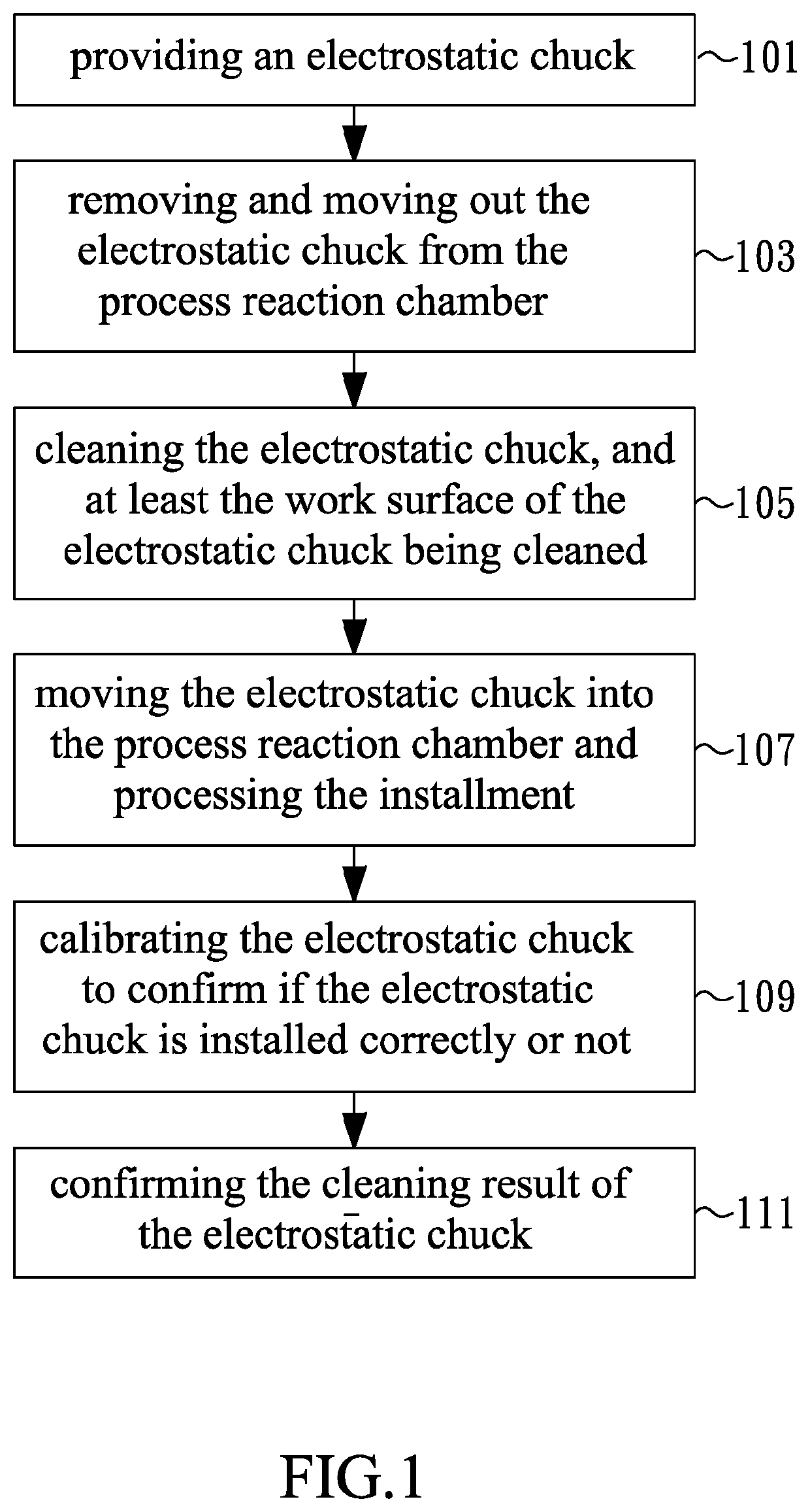
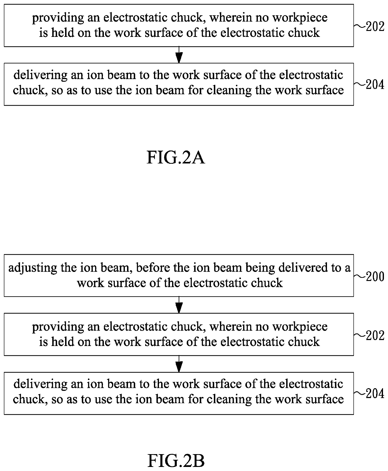
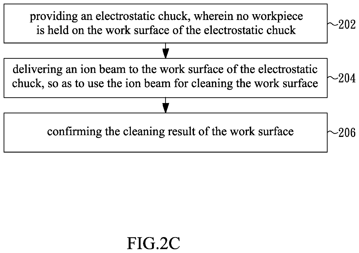
[0018]The present invention is based on the concept of cleaning the electrostatic chuck without moving the electrostatic chuck out and in the process reaction chamber, so as to avoid the several disadvantages of the conventional method of cleaning the electrostatic chuck. In particular, as only the contamination (such as the deposition) existing on the work surface of the electrostatic chuck for holding the workpiece will affect the held strength between the electrostatic chuck and the w...


PUM


Abstract

A method of cleaning an electrostatic chuck (ESC) is disclosed. An ion beam is delivered to a work surface of an ESC where no workpiece is held. The interaction between the ion beam and the depositions on the work surface may remove the depositions away the ESC, no matter the interaction is physical bombardment and / or chemical reaction. Hence, the practical chucking force between the ESC and the held workpiece may be less affected by the depositions formed on the work surface during the period of holding no workpiece, no matter the photoresist dropped away the workpiece and / or the particles inside the process chamber. Depends on the details of the depositions, such as the structure, the thickness and the material, the details of ion beam may be correspondingly adjusted, such as the ion beam current, the ion beam energy and the kinds of ions. For example, a low energy ion beam may be used to reduce the potential damages on work surface of the ESC. For example, both the oxygen and the inert gas may be used to generate the ion beam for removing the depositions and protecting the dielectric layer inside the work surface of the ESC.

Description

CROSS-REFERENCE TO RELATED APPLICATIONS[0001]The entire contents of Taiwan Patent Application No. 104135345, filed on Oct. 28, 2015, from which this application claims priority, are incorporated herein by reference.BACKGROUND OF THE INVENTION1. Field of the Invention[0002]The present invention generally relates to a method of cleaning an electrostatic chuck, and more particularly to a method of delivering an ion beam to a work surface of the electrostatic chuck, which is used for holding a workpiece, so as to remove the deposition from the work surface.2. Description of Related Art[0003]The ion implantation is to deliver dopants into the material in order to change the character of the material, such as adding trivalent element ions and / or pentavalent element ions to improve the conductivity of the non-conductive material. In recent years, the ion implantation is commonly used, such as in the processes for integrated circuits, memories, light emitting diodes, solar cells, flat panel...

Claims


Application Information

Patent Timeline
Patent Type & Authority Patents(United States)
IPC IPC(8): H01J37/30B08B7/00H01L21/683H01J37/20H02N13/00H01J37/304
CPCB08B7/00H02N13/00H01J37/30H01L21/6833H01J37/20H01J2237/2002H01J2237/30466H01J2237/022H01J37/304B08B7/0035B08B11/04H01L21/6831H01L21/02046H01L21/265H01L21/6704
Inventor NI, YU-HOKANG, CHUN-CHINYANG, CHIEH-JEN
Owner ADVANCED ION BEAM TECHNOLOGY INC
Why Eureka
Try Eureka