Planar ultrawideband modular antenna array having improved bandwidth

a technology of modular antenna arrays and antenna arrays, applied in the field of antenna arrays, ultrawideband (uwb) wireless communication systems, can solve problems such as significant structural differences, achieve the effects of reducing common-mode disruptive, avoiding induction, and improving bandwidth and frequency scalability potential

Active Publication Date: 2020-08-11
THE UNITED STATES OF AMERICA AS REPRESENTED BY THE SECRETARY OF THE NAVY +1
View PDF9 Cites 3 Cited by
  • Summary
  • Abstract
  • Description
  • Claims
  • Application Information

AI Technical Summary

Benefits of technology

[0011]Additionally, according to certain embodiments, metallic ribs are attached to the fed and grounded lines beneath the horizontal dipole segments and oriented towards one another to enhance capacitive coupling and improve impedance performance in the transition from the feed circuits to the dipole traces. The heightened capacitance between the dipoles and feed lines also enables wider trace-trace gaps, via-to-via distances, via diameter-to-height aspect ratios, and thicker dielectric materials to be utilized that satisfy PCB standard manufacturing tolerances up to approximately Q-band (50 GHz).
[0012]Due to these simple yet innovative new features, embodiments of the PUMA arrays disclosed herein retain the practical mechanical benefits of conventional PUMA arrays (e.g., modularity, direct unbalanced feeding, planar fabrication, low-profile, etc.) while doubling the bandwidth (3:1 to 6:1) to yield a fractional bandwidth of 143% (as opposed to 100%). An additional attractive feature of the PUMA array according to certain aspects and embodiments is that its frequency operation can extend up to the grading lobe frequency (i.e. Dx=Dy=λ / 2 for scanned arrays, where Dx and Dy are the array periodicity in the lateral dimension and λ is the free space wavelength), thus optimally sampling the array aperture, which implies the use of the least number of elements and electronics. The fully planar topology of embodiments of the PUMA arrays disclosed herein enables standard microwave / millimeter-wave fabrication to produce low-cost, low-profile (λh / 2, where λh is the highest frequency wavelength), modular UWB-ESAs with a competitive 6:1 bandwidth.
[0013]According to one embodiment, a PUMA array having enhanced bandwidth and frequency scalability comprises an unbalanced RF interface, a dual-offset dual-polarized lattice of horizontal dipole segments directly fed with the unbalanced RF interface, and a metallic plate capacitively-coupled to the lattice of horizontal dipole segments and pinned to ground with a plated via.

Problems solved by technology

However, there are several significant structural differences as compared to conventional PUMA arrays.

Method used


Image

  • Planar ultrawideband modular antenna array having improved bandwidth
  • Planar ultrawideband modular antenna array having improved bandwidth
  • Planar ultrawideband modular antenna array having improved bandwidth

Examples


Embodiment Construction

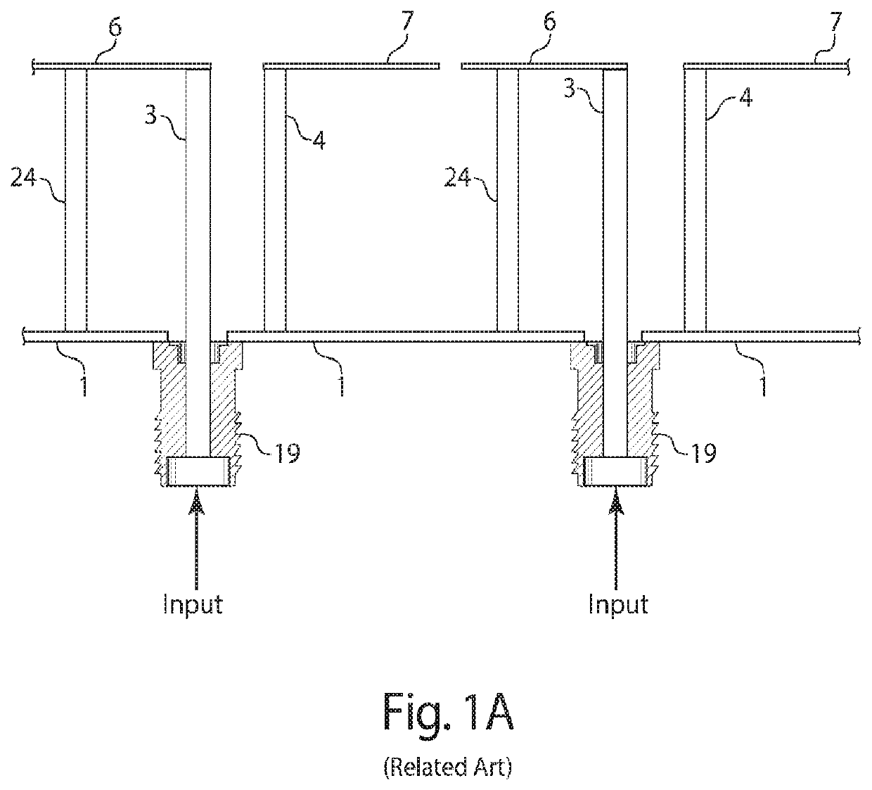
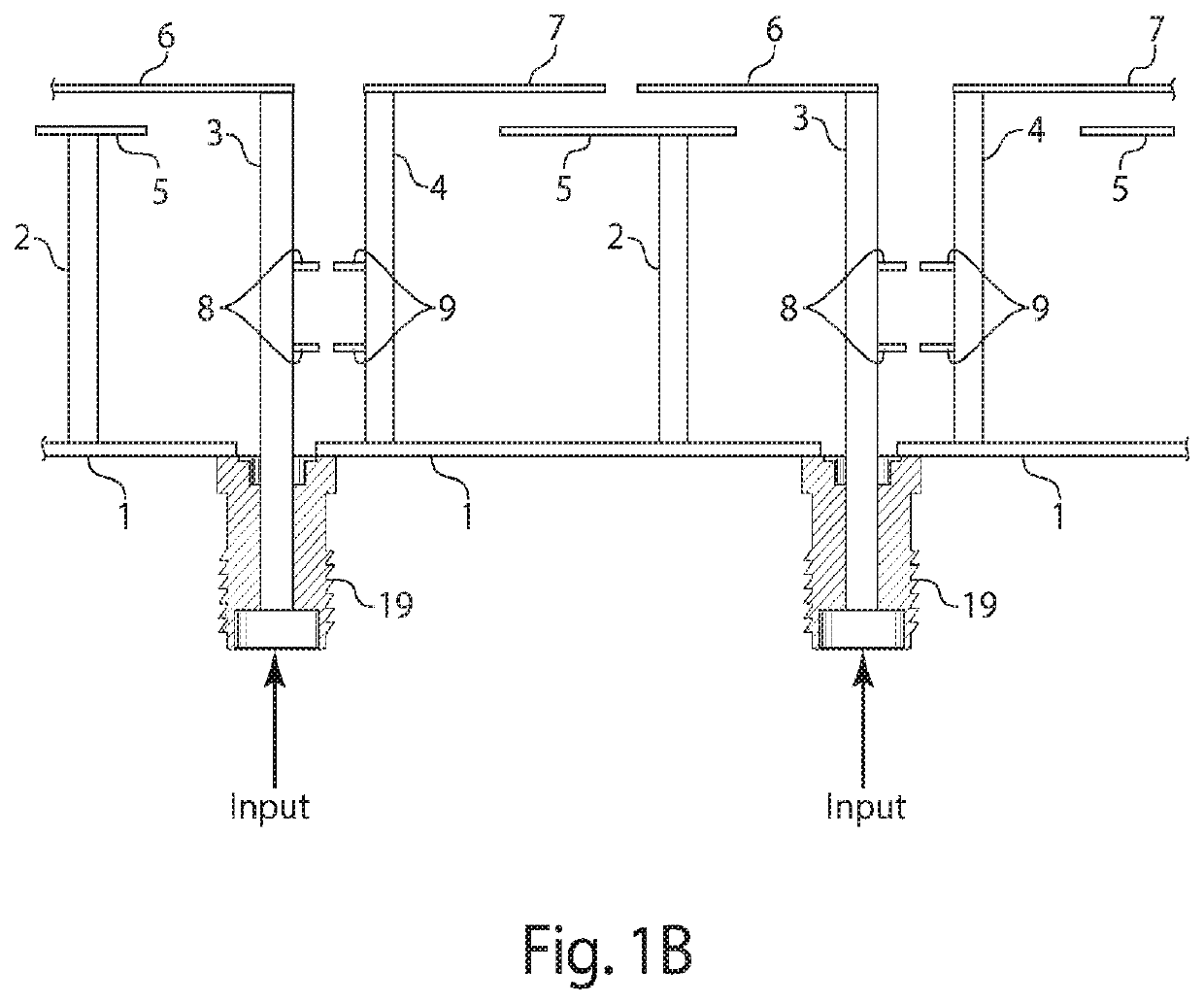
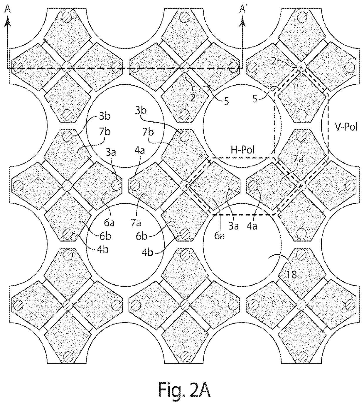
[0050]Aspects and embodiments are directed to a new class of Planar Ultrawideband Modular Antenna (PUMA) arrays with enhanced bandwidth and frequency scalability potential. In particular, certain embodiments provide a PUMA array with double the bandwidth as compared to a conventional PUMA array of similar size and similar type of feeding circuitry. This increase in bandwidth is achieved through implementation of various unique architectural features, as discussed in more detail below. Furthermore embodiments of the array remain simple to fabricate using standard microwave fabrication techniques up to EHF (mm-wave) frequency bands, while providing significant performance enhancements over conventional PUMA arrays. When advanced manufacturing technologies such as lithographic processing on hard substrates are used, some PUMA array features such as printing art and vias can be placed closer thus embodiments of the PUMA array disclosed herein can be manufactured up to frequencies that e...


PUM


Abstract

Structures and configurations for planar ultrawideband modular antenna arrays. One example of a PUMA array includes an unbalanced RF interface, a lattice of horizontal dipole segments directly fed with the unbalanced RF interface, the lattice being arranged in either a dual-offset dual-polarized configuration or a single-polarization configuration, and a metallic plate capacitively-coupled to the lattice of horizontal dipole segments and pinned to a ground plane with a first plated via.

Description

CROSS-REFERENCE TO RELATED APPLICATIONS[0001]This application claims priority to and the benefit under 35 U.S.C. § 119(e) of U.S. Provisional Application No. 62 / 121,055 titled “IMPROVED BANDWIDTH PLANAR ULTRAWIDEBAND MODULAR ANTENNA ARRAY” and filed on Feb. 26, 2015, which is herein incorporated by reference in its entirety for all purposes.FEDERALLY SPONSORED RESEARCH[0002]This invention was made with government support under grant No. N00173-13-1-G015 awarded by the Naval Research Laboratory. The U.S. government has certain rights in the invention.FIELD OF THE INVENTION[0003]Aspects and embodiments relate generally to antennas, antenna arrays, ultrawideband (UWB) wireless communication systems, remote sensing, RADARs, electronic warfare, and multifunctional systems.BACKGROUND[0004]Ultrawideband electronically scanned arrays (UWB-ESAs) with polarization agility and wide-scan performance remain as a key component in programmable and multifunctional RF front-end systems. Additionally...

Claims


Application Information

Patent Timeline
Patent Type & Authority Patents(United States)
IPC IPC(8): H01Q5/25H01Q5/42H01Q5/48H01Q21/06H01Q21/24H01Q9/28H01Q9/06
CPCH01Q21/062H01Q5/25H01Q5/42H01Q9/065H01Q9/285H01Q5/48H01Q21/24
Inventor VOUVAKIS, MARINOS N.KINDT, RICK W.LOGAN, JOHN T.
Owner THE UNITED STATES OF AMERICA AS REPRESENTED BY THE SECRETARY OF THE NAVY
Why Eureka
Try Eureka