Catheter comprising PTFE liner

a thin wall catheter and ptfe technology, which is applied in the direction of catheters, other medical devices, coatings, etc., can solve the problems of affecting the service life of the catheter, the damage to the liner, and the difficulty of delivering the device therethrough, so as to achieve the effect of low tensile modulus, similar flexibility and easy maintenan

Active Publication Date: 2020-08-18
ZEUS COMPANY INC
View PDF5 Cites 2 Cited by
  • Summary
  • Abstract
  • Description
  • Claims
  • Application Information

AI Technical Summary

Benefits of technology

[0006]The disclosure provides an extruded polytetrafluoroethylene (PTFE) tube with an average wall thickness less than 0.001 inches, with limited machine direction orientation of PTFE fibrils (resulting in an intermediate tensile strength and low tensile modulus). Due to the very thin walls of the disclosed tubes and the low modulus values of such tubes, they can, in some embodiments, desirably have similar flexibility as dip-coated PTFE liners, but can exhibit better ID lubricity and abrasion resistance than the dip-coated PTFE liners. The combination of properties exhibited by the disclosed tubes, in various embodiments, can render them particularly suitable for use within catheters, including within catheters designed for flexibility, as the thin wall thicknesses and low modulus values of the disclosed tubes provide for a significantly more flexible tube / liner product than traditional thin wall extruded (“free extruded”) PTFE liners, as will be described in further detail herein below. It is noted that portions of the specification are described with particular reference to such tubes as catheter liners; however, the tubes and methods disclosed herein are understood to be applicable in other contexts as well, and are not limited to use in catheters.

Problems solved by technology

If the catheter ID is not of sufficient lubricity, devices such as stents can cause damage to the liner as the devices are pushed through the catheter lumen.
The compressed shape exerts an outward radial force, which causes friction with the ID, commonly making delivery of the device therethrough difficult.
Known PTFE-based materials for use within catheter applications suffer from various drawbacks.
For example, certain extruded PTFE tubes can be produced with sufficiently thin walls and sufficiently high tensile strengths, but exhibit high rigidities and high tensile modulus values, rendering them unsuitable, e.g., in applications where flexibility is important.
Similarly, modified extruded PTFE tubes have been reported with high tensile strength, but undesirable stiffness, due to the method by which the high tensile strength was obtained.
Additionally, dip-coating methods are known to be cumbersome and suffer from low productivity (requiring repeated coating / sintering steps).
Further, dip-coated tubes typically have relatively low abrasion resistance, as a result of separation of PTFE particles and, as such, the ID of these tubes often have inferior lubricity properties.

Method used


Image

  • Catheter comprising PTFE liner
  • Catheter comprising PTFE liner
  • Catheter comprising PTFE liner

Examples


example 1

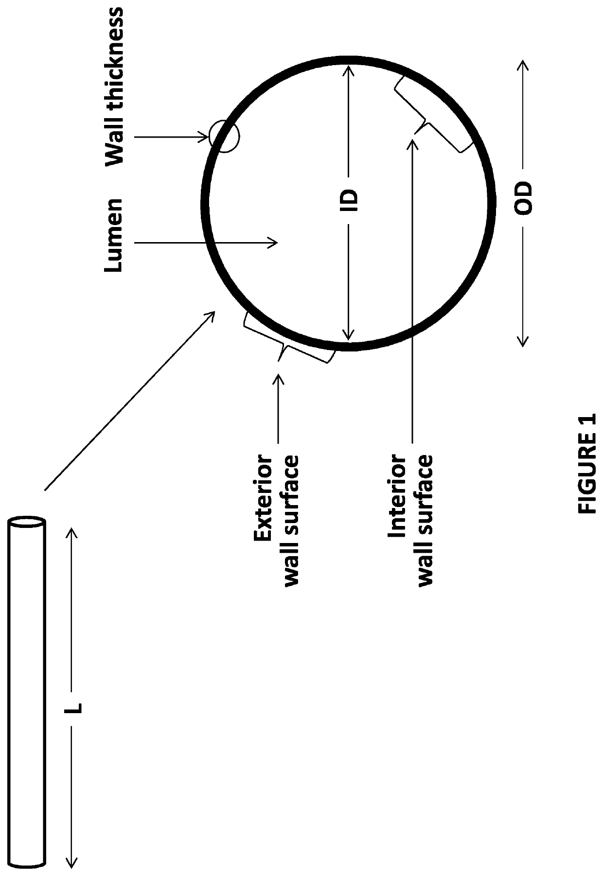
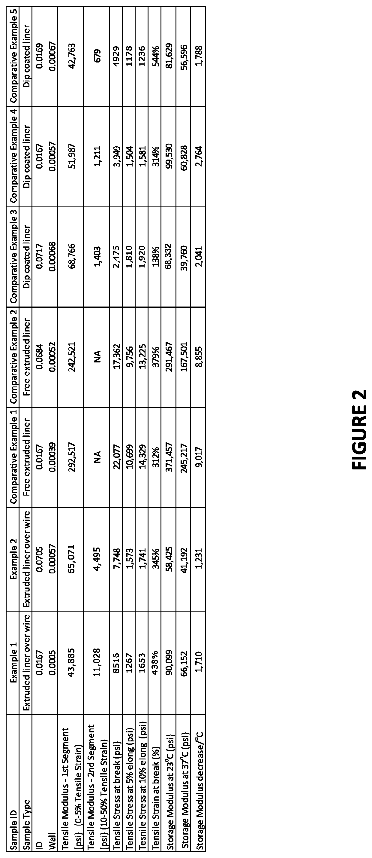
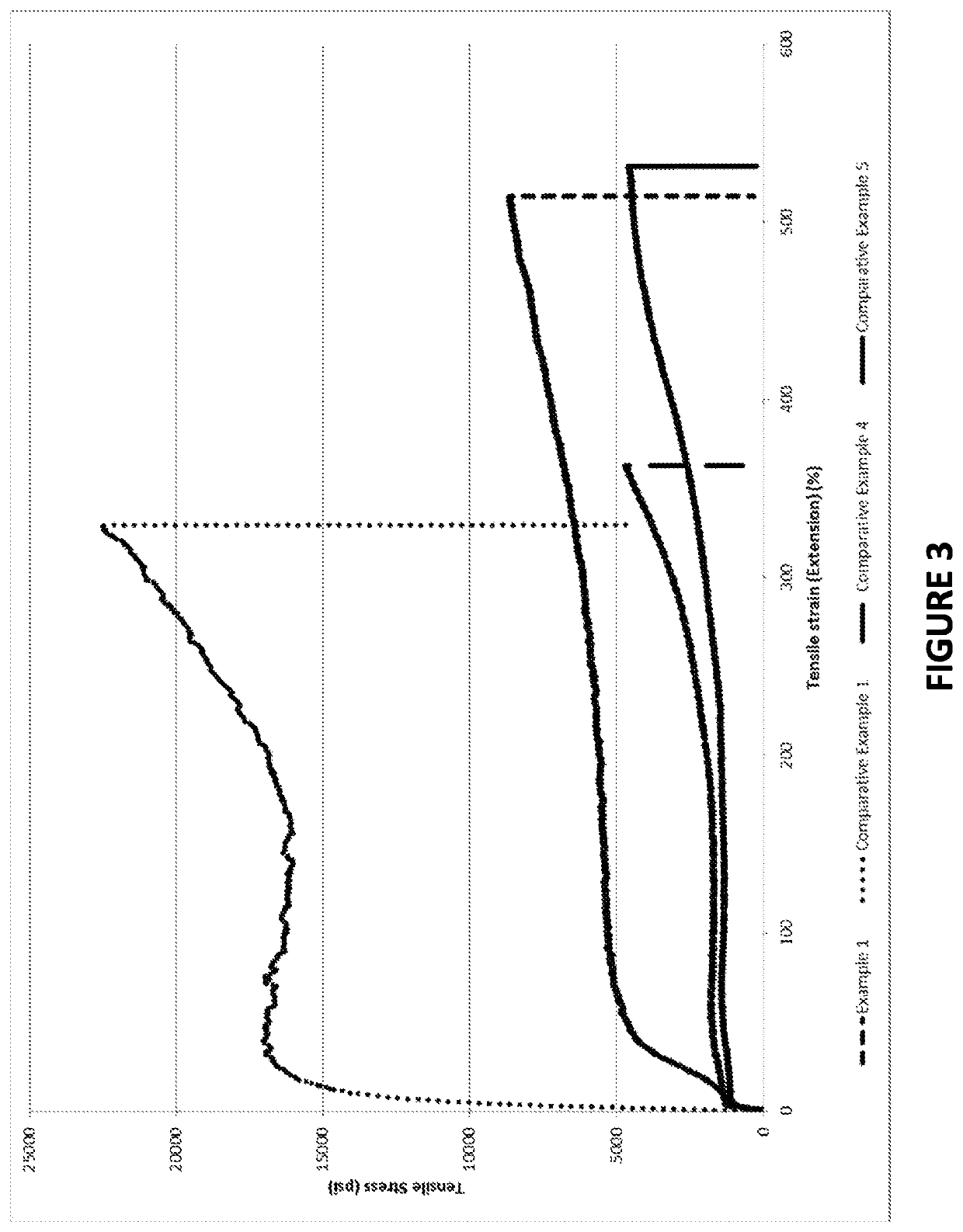
[0067]A PTFE paste extrusion process was employed (using a medium to high reduction ratio lower MW resin grade) to extrude a 0.0005″ thick PTFE layer over an annealed copper wire of 0.0169″ OD, followed by devolatilazation of lubricant and sintering of PTFE over the wire. The PTFE layer thickness was determined as follows. The outer diameter (OD) of the coated wire was measured with a laser. The PTFE coating was removed at one location without stretching the wire. The OD of the exposed wire was then measured by laser. Based on these OD readings, the wall thickness of the PTFE tube was calculated. It was ensured that no air gaps are present between the wire and the PTFE layer and coating was smooth and bonded well with the wire. The annealed coated wire was then stretched as described above and the PTFE coating (in tubular form) was removed from the wire without deforming or damaging the PTFE layer to give a free-standing PTFE product in tubular form. This sample was then cut to appr...

example 2

[0068]The process described in Example 1 was also employed to produce a PTFE tube, with the only exception being that the metallic core used was an annealed copper wire with outer diameter / OD of 0.071″. Tensile and DMA tests were also performed on this sample. See FIGS. 5 and 6.


PUM

PropertyMeasurementUnit
thicknessaaaaaaaaaa
tensile stress at breakaaaaaaaaaa
storage modulusaaaaaaaaaa

Abstract

The present disclosure provides catheters comprising polytetrafluoroethylene (PTFE) tubes with advantageous combinations of strength, flexibility, and size. Such tubes can exhibit features including an average wall thickness of 0.001″ or less, a tensile stress at break of greater than 5000 psi, and a storage modulus of less than 100,000 psi at 37° C. These tubes can be also be provided independently (i.e., not within a catheter) and can be employed in various applications.

Description

FIELD OF THE INVENTION[0001]The present application relates generally to the field of catheters comprising thin wall catheter liners comprising poly(tetrafluoroethylene) (PTFE) and to methods relating to such catheters.BACKGROUND OF THE INVENTION[0002]Vascular therapy uses minimally invasive, catheter-based procedures and specialized equipment and techniques. Catheters used in these procedures commonly employ a coating or liner on the inner wall to provide a smooth inner surface. A smooth inside diameter (ID) associated with these devices is beneficial in reducing friction against various catheter technologies such as stents, balloons, atherectomy or thrombectomy devices as they are pushed through the tight confines of the catheter lumen. If the catheter ID is not of sufficient lubricity, devices such as stents can cause damage to the liner as the devices are pushed through the catheter lumen. The effect of increased lubricity of the catheter ID is a reduced deployment force of cath...

Claims


Application Information

Patent Timeline
Patent Type & Authority Patents(United States)
IPC IPC(8): A61M25/00A61L29/08A61L29/14A61L29/12A61L29/02
CPCA61L29/14A61L29/02A61L29/085A61M2025/0047A61M2205/0222A61L2400/10A61L29/041C08L27/18A61M25/0045A61M2025/0062
Inventor WAHAB, ZAHIDULALPIZAR, GUILLERMOCOOPER, PATRICKCOX, JEFFREY M.GONZALEZ, LAURENCE C.GREEN, DANIELRAST, EDWARDSALVADOR, BERNARDSINGH, RAVINDERTOURVILLE, DOUGLASVILLAGRA, FRANKLIN
Owner ZEUS COMPANY INC
Why Eureka
Try Eureka